Transistor circuit help

AfdhalAtiffTan

Joined Nov 20, 2010
120
Yes thank you.

But it seems something odd is happening. When I apply a current to the base of the transistor the led lights up but I can't see how it does as the collector isn't connected to the positive rail(??)

I assumed the base current allowed a current to flow from collector to emitter but I've noticed the collector isn't actually connected to a the positive rail at the moment. :s
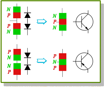
It's because transistor can be behave like two diodes connected together; like this:


In other words, the transistor is now behaving like a diode, with no current amplification.

Try to connect the collector to positive rail, and the base current will drop. :)
 

Thread Starter

8-bit

Joined Jan 7, 2014
27
Many thanks for the reply.

I just wanted to set up a circuit that shows the transistor as a switch but it is not working like that. It seem from my circuit that the current is just flowing straight through it via the base. Maybe the transistor is faulty?
 

Thread Starter

8-bit

Joined Jan 7, 2014
27
I don't what has changed but it is working as it should now. The LED only lights when a current it put through the base of the transistor. Maybe it was a bad connection somewhere?

Thanks for every bodies help and guidance. :)
 

WBahn

Joined Mar 31, 2012
33,332
I did not think that it would be able to short as no current can flow between the collector and emitter until the transistor is 'turned on' by a base current.(?)
If you just pull the transistor out you will see that the LED still lights up. The current is going through the strip of metal and your transistor is just sitting there looking stupid.

After fixing that, another thing to get in the habit of is not leaving base inputs floating. Some transistors will have enough leakage current to provide their own base current if you do. Instead, do something to take the base-emitter voltage to something less than the half volt or so needed to start turning it on. As someone mentioned previously, tying it to the emitter will work fine if that is a practical option.
 
Am I missing how this style breadboard works? Are 2 legs of the transistor on the same rail? I use different style boards, but this seams like an odd configuration.
 
Here are two different ways you can use an NPN transistor to switch a LED.
What is the reason for not needing the 4.7KR to trigger the 2222 in the latter section of the diagram? I am fairly new to electronics, and have only been using 2222's to "Switch ground", so I have just started playing with them in that manner, so I am curious as to why the needs are different.
 

Thread Starter

8-bit

Joined Jan 7, 2014
27
Am I missing how this style breadboard works? Are 2 legs of the transistor on the same rail? I use different style boards, but this seams like an odd configuration.
They are yes, they are bridging the gap between two rails now that I moved it slightly.


I'm now thinking of playing around with it a little now. Could I insert a photo resistor into the circuit so that 'light' would switch the transistor on and off?
 
They are yes, they are bridging the gap between two rails now that I moved it slightly.


I'm now thinking of playing around with it a little now. Could I insert a photo resistor into the circuit so that 'light' would switch the transistor on and off?
I am curious about the phototransistor thing myself. I often use photoresistors, and temp sensors inline with another resistor as a voltage divider to signal either an op-amp or comparator against the voltage "Trigger point" of a potentiometer. I have been thinking about setting a trigger pint with a zener diode tonight without a comparator at all. Like triggering a circuit if the voltage gets above/below 5.1V if a 5.1V zener diode is used as a reference some how?
 
Top