Timed LED lights (like drag racing "Christmas Tree" starting lights)

Bernard

Joined Aug 7, 2008
5,784
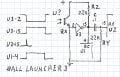
BALL LAUNCHER 3 00000.jpg When the ball falls in it is held for the full 3 sec. so U2-15, reset, should be held high for just a short time.
Time out for eyeball simulation.
Assuming emitter follower as input, with no ball signal is hi, with ball, sig. is low for 3 sec. Inverted , clock is enabled for 3 sec, leading edge is differentiated to give a short + pulse to reset U2. It may be best to shift all U2 outputs down one stage as the first clock will be blanked by reset.
 
Last edited:

Thread Starter

CaptStephan

Joined Feb 14, 2018
34
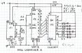
OK, feeling like I have forgotten more than I thought from my college circuits class. So, here is a stupid question I am sure: Looking at the diagram in #58, IC 4017B, there is a line from 8 to ground and from 13 to ground, but the line from 13 to ground has a little circle on it that implies some sort of single pole connection. I don't understand the difference between the two?

Thanks in advance gang,
Stephan
 

Thread Starter

CaptStephan

Joined Feb 14, 2018
34
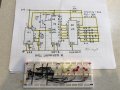
Highlighted parts are assembled on this board. A little advice on my last post and if I am correct I can just put power to U2-15 to test it?
 

Attachments

Bernard

Joined Aug 7, 2008
5,784
RE U2-8. Vss is - power supply; U2-13 is clock enable, active when lo as indicated by the little circle.
To be consistent then there should be a circle on U1-2.
Note, top of R1 & R2 should go to +9V.
For testing , I would connect top of R2 to ground. To reset, a momentary touch of a lead from +9V to U2-15.
I can't follow all leads on photo but wondering if U1-1 & U2-8 go to ground?
 

Bernard

Joined Aug 7, 2008
5,784
Another option would be the motor leads as they start when the ball drops. One side
prob. tied to either ground or + supply other can be shaped as start sig.
On U2, reset is pin 15, the 1 got chopped off.
On my bread board , another LED & R were added to U3-15 & one to U1-3 with cathode to ground to monitor operation.
On power-up , one or more stages on U2 will come on requiring up to 6 sec. to clear. Is this acceptable ?
 
Last edited:

Thread Starter

CaptStephan

Joined Feb 14, 2018
34
I like the motor idea, I was already thinking about that as it is super easy access and it does give +9v.

No problem with the delay on reset as it takes a while to get the ball back to the device.

I will update my board tonight - did you see my red-line on U1-1 vs U1-8? I think I have it correct based on the chip diagram.
 

Bernard

Joined Aug 7, 2008
5,784
My bad- power still goes to pin 8.
Should be easy- connect hot motor lead thru a .1 uF cap. to U2-15, reset RE post # 65.
The long delay only happens once at turn on, no ball launch.
 

Thread Starter

CaptStephan

Joined Feb 14, 2018
34
OK, I am totally not understanding how this darn ball throwing board works!! Reference my earlier posts about wire colors, but I took it apart again and tried everything under the sun, here are the results:
  • Power In = +9.13v (center pole of plug is +9v and outer rim of plug is -, which I am calling ground).
  • Either motor pole to ground = +9.13v when running or off either way.
  • From one motor pole to the other = 0v when off and +2.34v when running.
  • Optical switch is either too fast for me to see on my little multi-meter or I don't get it at all.
    • Red to White/Green is +0.8v plus minus 0.2v (it bounces around a lot) when no ball is in place and +1.0v when a ball is in place (very steady).
    • Same exact result for Yellow to White/Green.
    • Red to Yellow = nothing at all either way.
    • I accidentally crossed the yellow to the pin with no wire on it and the sequence started. Not sure what that means, but no voltage was there in either state.
So, I guess the question becomes this: could we somehow use the +2.34 volts?

Also, am I doing something stupid and missing the point here?

Thanks,
Stephan
 

Thread Starter

CaptStephan

Joined Feb 14, 2018
34
RE U2-8. Vss is - power supply; U2-13 is clock enable, active when lo as indicated by the little circle.
To be consistent then there should be a circle on U1-2.
Note, top of R1 & R2 should go to +9V.
For testing , I would connect top of R2 to ground. To reset, a momentary touch of a lead from +9V to U2-15.
I can't follow all leads on photo but wondering if U1-1 & U2-8 go to ground?
I forgot to answer your questions on #64. U1-1 was to ground, but U2-8 was not, I missed that. Fixed it now.
 

Bernard

Joined Aug 7, 2008
5,784
Maybe I'm just getting old, but I can't make sense of any of the measurements except the 2.34V across a motor. The low value suggests that motor is driven by a PWM , pulse width modulation, signal ? Could motors be in series ? If all else fails then we can use the 2.34 V signal, but it would be nice if it were referenced to either ground or + supply.
 

Thread Starter

CaptStephan

Joined Feb 14, 2018
34
Same here. I think we lost the crowd on this one ☹. Can’t figure that damn thing out. Starting to think a whole separate trigger idea might be better.
 

Bernard

Joined Aug 7, 2008
5,784
If it comes to an external trigger it is doable. Seems that there is enough space on inner throat just above the vanes for two 5 mm sensors. Tx something like VSLY5850-ND, 850 nm, or
LTE-2871, 940 nm., no # for Rx, all that I have are surface mount.
Any idea of how much space there is between outer shell & top of throat ?
 

Thread Starter

CaptStephan

Joined Feb 14, 2018
34
I think about 1/2” near the narrow middle part. Less near the top as it transitions to the horizontal part.

I did take a long shot and emailed iFetch to see if they would help out. Not sure that will go anywhere.
 

Thread Starter

CaptStephan

Joined Feb 14, 2018
34
@AnalogKid - Looking at your post #60 in this thread, could you elaborate as if you were speaking to a complete amateur on how you would manually test you circuit? I tried the one Bernard posted with his modifications and just couldn't get there. I then put yours together today and I get the first lights on, but nothing else. I suspect it is because I am not triggering it correctly. Thanks in advance, Stephan
 

AnalogKid

Joined Aug 1, 2013
12,238
Post #60 refers to the schematic in post #30, and that one is incomplete. For the most basic testing you will need one switch (just about anything will work) and one resistor, 1K to 100K.

First, what test equipment do you have?

ak
 
Last edited:

Thread Starter

CaptStephan

Joined Feb 14, 2018
34
Post #60 refers to the schematic in post #30, and that one is incomplete. For the most basic testing you will need one switch (just about anything will work) and one resistor, 1K to 100K.

First, what test equipment do you have?

ak
I have a digital multimeter, but that is about it.
 
Top