@AnalogKid I timed it and it is 3 seconds on the money.
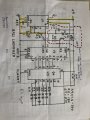
Yes, that is good for the schematics in 30 and 31.is this the right timer?
The part values in post #30 might be a bit fast. Increase R1 to slow it down. The oscillation frequency is:@AnalogKid I timed it and it is 3 seconds on the money.
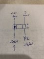
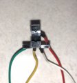
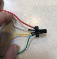
I think you are correct about the trigger. I disassembled the entire thing and noted the markings shown in the attached. When the unit is plugged in and on, I see +3.2 V from red to common and from yellow to common. I can't get to the white or green easily, but they are tied to the same pin on the main board. Thoughts?Nice videos. The trigger is an opto-interrupter. Two wires should be DC driving the LED and two wires are the output transistor coming back to the control board as a switch. These are the ones we want to tap into. Beethoven tonight, more later.
ak

No, they're not. The image in #49 shows that the anode of the LED and the collector so the phototransistor both are connected to 3.2 V. For now, let's assume that that is the system power voltage, Vcc.OK, I did a little homework about how these opt-interrupers work. I have to assume that the inlet resistor for the LED is on the board. The power to each side is 3.2V. The issue I am having is that the two outlets are tied together.

| Thread starter | Similar threads | Forum | Replies | Date |
|---|---|---|---|---|
|
|
Help with a hall effector timed LED change | General Electronics Chat | 34 | |
| J | 12 vdc timed momentary | Power Electronics | 7 | |
|
|
Timed 3V circuit... | Digital Design | 13 | |
| D | I need a timed switch for 12VDC motor. | Power Electronics | 3 | |
|
|
Need a new project. Have temperature sensitive timed switches. | General Electronics Chat | 5 |