Timed LED lights (like drag racing "Christmas Tree" starting lights)

AnalogKid

Joined Aug 1, 2013
12,238
Nice videos. The trigger is an opto-interrupter. Two wires should be DC driving the LED and two wires are the output transistor coming back to the control board as a switch. These are the ones we want to tap into. Beethoven tonight, more later.

ak
 

AnalogKid

Joined Aug 1, 2013
12,238
@AnalogKid I timed it and it is 3 seconds on the money.
The part values in post #30 might be a bit fast. Increase R1 to slow it down. The oscillation frequency is:
f = 1 / ( 1.4 x R x C )
which is 0.7 RC for each half cycle. But the first half cycle is 1.1 RC, so that adds just under 5% to the overall 6-cycle period. Increasing R1 to 330 K yields a calculated 6-cycle period of 2.9 seconds.

ak
 
Last edited:

Thread Starter

CaptStephan

Joined Feb 14, 2018
34
Nice videos. The trigger is an opto-interrupter. Two wires should be DC driving the LED and two wires are the output transistor coming back to the control board as a switch. These are the ones we want to tap into. Beethoven tonight, more later.

ak
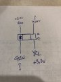
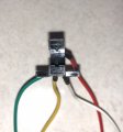
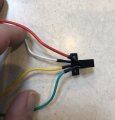
I think you are correct about the trigger. I disassembled the entire thing and noted the markings shown in the attached. When the unit is plugged in and on, I see +3.2 V from red to common and from yellow to common. I can't get to the white or green easily, but they are tied to the same pin on the main board. Thoughts?
 

Attachments

Thread Starter

CaptStephan

Joined Feb 14, 2018
34
OK, I did a little homework about how these opt-interrupers work. I have to assume that the inlet resistor for the LED is on the board. The power to each side is 3.2V. The issue I am having is that the two outlets are tied together. In all of the examples I found, one should be tied directly to ground and the other should be my signal, but with a pull-down resistor to ground. I don't see how this one could have the pulldown resistor to ground as the two wires are tied together on the same pin in the plug. If I understand how this thing works, there should be a resistor between them.

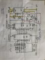
All that said, I can't figure out how this should be wired to the circuit outlined above. I think it replaces part of the circuit diagram I have outlined in red, but correct me if I am wrong.IMG_0351.JPG
 

AnalogKid

Joined Aug 1, 2013
12,238
OK, I did a little homework about how these opt-interrupers work. I have to assume that the inlet resistor for the LED is on the board. The power to each side is 3.2V. The issue I am having is that the two outlets are tied together.
No, they're not. The image in #49 shows that the anode of the LED and the collector so the phototransistor both are connected to 3.2 V. For now, let's assume that that is the system power voltage, Vcc.

For the LED, the anode is the "inlet". Another relatively safe assumption is that the current limiting resistor from the cathode to GND is on the board. Don't know the value, don't care.

For the transistor - most optocoupler and opto-interrupter devices have an NPN transistor as the output device. So the collector (the "inlet") is connected to Vcc and the emitter is the "output". When the beam is visible to it, the transistor is a saturated switch pulling an external load resistor or circuit input high. When the beam is interrupted the tranistor turns off and whatever the external impedance and voltage are take over. My guess is that the load is a resistor to GND and an input pin of a CMOS device, probably a small microcontroller like a PIC. On paper, the transistor looks like it is an emitter-follower configuration, but because the "base" (the photo-receptive region) is not restricted from having a photo-voltaic potential that is greater than the voltage on the collector, the transistor can saturate even the load is on the emitter. This is a benefit of optocouplers that I think is way under-appreciated.

Therefore, it is the voltage from the emitter to either Vcc (white wire) or GND (no wire for that, have to find it on the pc board) that changes when the vane is moved, and that is the voltage we can tap. I'd prefer emitter-to-GND because that is easier to translate up to some other logic level, but we can work with either. The external circuit *will* have to share a common ground with the pc board, so locating a GND point is not optional.

Can you measure the white-red voltage before and after actuation?

ak
 
Last edited:

Thread Starter

CaptStephan

Joined Feb 14, 2018
34
I can. I will have to break the insulation on the white wire though, so I was avoiding that until I was sure I needed to do it.

I have a general ground located on the board from where the input power cable attaches to the board. I am assuming that point is OK to use for all "to ground" discussions?
 

Thread Starter

CaptStephan

Joined Feb 14, 2018
34
OK, I am super confused. Here are the readings:

Switch not interrupted:
White to ground = 3.00v
Red to ground = 3.20v
White to Red = 0.25 to 0.30v bouncing all around

Switch interrupted, no change on first two, but:
White to Red = 0.30v very steady
 
Last edited:

Thread Starter

CaptStephan

Joined Feb 14, 2018
34
It is a well drawn diagram, I should have no problems with it. I just don't know what goes to 15 on the 4017B.

I was using Bernard's hand drawing from #30 to get started for some reason, not sure why. There are some differences between the two, but I think I can follow the intent. I don't see power to the 4017B in your version and I haven't walked through it yet to make sure I fully understand the differences.
 

Bernard

Joined Aug 7, 2008
5,784
Thanks for all of the measurements, but we still need one that shows some action when sensor is blocked.
Measurements on yellow to common ?
I hope drawing is correct now. What we want is a + signal to U2-15, reset, when sensor is interrupted. Whatever the form of the signal, it can shaped to our needs.BALL LAUNCHER 2 00000.jpg
I should have left the beam break out, just confuses the issue now that we know of the existing interrupter.
 

Thread Starter

CaptStephan

Joined Feb 14, 2018
34
OK, so the parts came in tonight, so I thought I would start putting this thing together. I am going to work from the drawing in #58 above, but I was wondering about the one in #30? Are they really the same and I just haven't realized it yet?
 

AnalogKid

Joined Aug 1, 2013
12,238
They are functionally the same. the difference is in the way we reset the circuit and what output state the 555 starts in. Notice that I have the first lights driven by 4017 output "0", while his circuit starts with "1". That is because his circuit starts with a positive edge, so the 4017 in incremented in the first instant after coming out of reset. My circuit starts with the 555 already high when the 4017 reset is removed, so it doesn't increment until the next 555 low-to-high transition at the end of the first cycle. I think mine uses 1 fewer resistor.

Both circuits rely on one of the 4017 outputs looping back at the end of the cycle, and inhibiting counting until it is reset by the external signal.

ak
 
Top