Facebook
 Google
 GitHub
 Linkedin
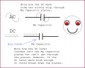
Hi all
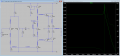
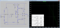
I was dimensioning the CE capacitor. To do that I was looking at some formulas seen in class. I wanted to compare such capacitor with the one proposed by Jony130. The formula (freq_C=1/(2*pi*Req*C) ) involves the knowledge of the loop gain (open loop gain*beta). It appears to be negative in my schematic. What does it mean? Is something wrong? In a different exercise in class I got a positive number: I though positive numbers were to be expected.
I was dimensioning the CE capacitor. To do that I was looking at some formulas seen in class. I wanted to compare such capacitor with the one proposed by Jony130. The formula (freq_C=1/(2*pi*Req*C) ) involves the knowledge of the loop gain (open loop gain*beta). It appears to be negative in my schematic. What does it mean? Is something wrong? In a different exercise in class I got a positive number: I though positive numbers were to be expected.
Attachments
-
4.3 KB Views: 6
-
 70 KB Views: 9
 -
 60.2 KB Views: 7
 -
3.4 KB Views: 4
Last edited: