Facebook
 Google
 GitHub
 Linkedin
Hello everyone, I am wondering what is a good way to sense both the current and voltage of a three-phase inverter DC bus.
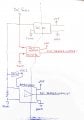
I have come up with a diagram like this, but I would like to hear your opinion.
I am afraid that resistances much greater than a few mΩ on the DC bus will affect the current flowing and/or the voltage... am I wrong?
Current sensing is fairly standard, while voltage sensing (in the picture) involves a classic resistive divider with an amplifier.
.jpg")
I have come up with a diagram like this, but I would like to hear your opinion.
I am afraid that resistances much greater than a few mΩ on the DC bus will affect the current flowing and/or the voltage... am I wrong?
Current sensing is fairly standard, while voltage sensing (in the picture) involves a classic resistive divider with an amplifier.


")