Sensing Current and Voltage of DC BUS three-phase inverter

panic mode

Joined Oct 10, 2011
5,189
how does point 2. create galvanic isolation?

2. Use a microcontroller to generate pulses that conform to some digital standard like 16 bit binary, or even a set of BCD digits with ASCII encoding.
using digital signals to transfer data is not isolated... unless... one deliberately adds isolation (optical, capacitive, inductive).
but advantage of using microcontrollers and data in digital form is that many signals can be transferred using the same isolation "bridge" or "border crossing".
so one can later on add more signals without redesigning hardware.

this is not the case with other options. every signal needs own isolation - for every analog value (voltage or current) another isolated OpAmp is needed. for every digital signal , another optocoupler is needed.

also this is cleaner and easier to troubleshoot and fix ... one need to only look at single transfer point.
 
Last edited:

Thread Starter

andrew74

Joined Jul 25, 2022
263
you know the best what works for you and your application requirements.

my experience is with industrial equipment and i stated in #32 why i would use different way to derive power.

similarly measuring motor phases is more direct. but... it also matters what are you trying to do with it.
Hi, I was just wondering whether your solution from post #32 can be implemented entirely on a single PCB or not, because I didn’t quite understand from the block diagram .. there seem to be more pcbs
 

panic mode

Joined Oct 10, 2011
5,189
i am not sure what you mean. what does number of PCBs have to do with anything? or how did you deduce that there need to be more than one?

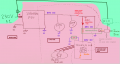
posts like #32, #33 etc. only show block diagram (an overview), not actual implementation. one of things i mentioned in #32 is choosing how the power is derived. deriving control power (like +5V for MCU) should not depend on situations that affect load.other posts who layouts that turn everything dark (And no diagnostics) if load kicks the bucket. to me this is unreasonable - i expect controls to work (report status, help with diagnostics,...) even if loads side (48VDC circuits) are pile of ash. for example anything in red area could be dead or missing and system could still offer diagnostics and help with troubleshooting. that is a mark of resilient system - to get status and some sort of damage control, one really only needs the green part. if the 5V for STM/display system was not separate (if it was derived from 48VDC), then failure in any single part of the entire system could lead to complete darkness (no response from the system, no diagnostics, no damage control)

1775652287534.png

back to number of PCBs. i think you are confusing protoboard in #33 (picture with Uno, INA1115 etc.) with final design, such as last image in same post. prototypes are just development platforms and modularity here is an asset (easy to adapt). final product is completely different animal and often it is a single larger PCB.
 

MrAl

Joined Jun 17, 2014
13,775
how does point 2. create galvanic isolation?


using digital signals to transfer data is not isolated... unless... one deliberately adds isolation (optical, capacitive, inductive).
but advantage of using microcontrollers and data in digital form is that many signals can be transferred using the same isolation "bridge" or "border corssing".
so one can later on add more signals without redesigning hardware.

this is not the case with other options. every signal needs own isolation - for every analog value (voltage or current) another isolated OpAmp is needed. for every digital signal , another optocoupler is needed.

also this is cleaner and easier to troubleshoot and fix ... one need to only look at single transfer point.
Yes I made that clear in previous posts where I also mentioned using a regular opto coupler.

I am not sure what you are saying about multiple signals. Each op amp would have to have it's own supply IF the inputs had to be isolated from each other. That does not seem to be the case here though.
 

panic mode

Joined Oct 10, 2011
5,189
this setup only needs those two zones, 48VDC (loads) and 5VDC (controls).

there is a bunch of signals:
DC bus voltage,
DC Bus current,
loads current,
BLDC phase current...

if the system is larger, more complex, there would be many more.

they all need to get from one zone (48VDC) to another (MCU).

one way is to transfer signals from one zone to another is to use isolated opamp (per analog signal) and optocoupler (per digital signal).
so if your system has 10 signals, you need at least 10 isolators. and when your system has even more signals (100s, 1000s...), you need more isolators, as shown in post #34.

this is pretty much the only option when no MCU is present. it is possible (but cumbersome) to multiplex and demultiplex signals without mcu. then multiplexed signal can be transferred using one or two optocouplers, even when number of exchanged signals is large. but the added complexity does not justify that approach when only few signals are used.

so far so good?

with MCU present, one has more flexibility because signals can be exchanged using some sort of bus (like I2C, SPI, RS232, RS422, whatever...).
in that case it, is enough to place part of the circuit (all sensing) into 48VDC zone. MCU and display are still on 5VDC side. using single isolator on that bus (and isolated supply) one can exchange many signals with ease. even if there is a design change, and one need to get something else (temperature etc), there is no need for more isolators.

encoding/decoding or multiplexing/demultiplexing takes time and really it is a trade-off... the larger block of data is, the longer the transfer and of course the slower refresh on any data point is.
 

MrAl

Joined Jun 17, 2014
13,775
Hello, and thank you for your detailed replies :)

-----------------------------------------------1° QUESTION (about the layout)--------------------------------------------------------------
I’m not 100% sure I’ve understood the final circuit ‘layout’, so I’ve redrawn it to clearly show that I need everything on a single PCB (whereas in the photo you attached in post #32, it looks as though there are several separate PCBs).

As I said, I want a three-phase motor driver that isolates the 48V from the microcontroller and the low-level logic (5V and 3V).

View attachment 365684

Let’s not focus on the choice of components for now (which DC-DC converter is best, which amplifier, etc.), but on the overall layout.
..for example for voltage sensing I drawn the AMC1311 but solutions such as the INA228 that you recommended might be much better (with the following I2C isolator)

@MrAi Sorry, but your two solutions, A and B, aren’t very clear to me; I’d need to try and sketch them out to understand (which I will do shortly).

What do you think of the circuit I’ve drawn?
At first, I didn’t want to use two isolated DC-DC converters because I thought they were all as large and bulky as the NCS6S4805, which would have taken up too much space..
But now I found some compact isolated solutions online, such as the TRACO TRN 1-48-11, which I could use just to power the op-amps (here we should ask ourselves whether its "low output wattage" is sufficient).
For everything else on the pcb I use the NCS6S4805 with its 5-6W.
I think this is the ‘simplest’ solution, and cost isn’t an issue.
What do you think?


----------------------------------------------2° QUESTION (about the components choice)------------------------------------------------
Let's assume I use ACS724LLCTR-10AU-T (0-10A) ... it produces [0,5 ... 4,5]V output that I need to send to a Texas Instruments C2000 microcontroller, which has a standard input range of 0 V to 3.3 V.

Do you agree with me that I should implement one of these:
- Resistive voltage divider: a step-down ratio of approximately 0.66 should convert the 4.5 V to approximately 3 V protecting the microcontroller pin
- Buffer with Op-Amp: a 3.3V op-amp in a buffer configuration with an input voltage divider that sould also 'clip' any dangerous spikes above 3.3 V


Thank you.

Hello again,

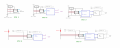
Here is a diagram showing five different ways to measure current.

Fig 1 has no isolation at all. The other ones Fig 2 and Fig 3 have output isolation used for measuring the 48v rail.
Fig 4 and Fig 5 have complete isolation for measuring something like an output that has no common ground. That would probably be your motor leads unless we can find a common ground.

Note isolating the op amp and the output may be necessary if the output has to be isolated as well as the input when measuring an arbitrarily placed current sense shunt. In that case the ground of the measuring circuit has to follow the negative lead of the shunt 'resistor'.

If you have a common ground somewhere that helps to reduce the necessity for something isolated.

Take a look at the five solutions and see if you can make sense of them. I would suggest understanding those circuits first before going any further so you can be sure of what you are doing. Once you learn the reasons behind this you could probably design your own circuit(s). That's just plain old circuit analysis at play.

Maybe @panic mode can take a look too and double check all five circuits. This is still a little tricky.
 

Attachments

panic mode

Joined Oct 10, 2011
5,189
the thread is at some 50 posts and i am still unclear what is the actual reason for those measurements, what sampling rate is needed. what accuracy... i think there was plenty of replies, tips and suggestions how things can be done. if there are still questions, or things that are unclear, things need to be narrowed down.. a lot.
 

MrAl

Joined Jun 17, 2014
13,775
the thread is at some 50 posts and i am still unclear what is the actual reason for those measurements, what sampling rate is needed. what accuracy... i think there was plenty of replies, tips and suggestions how things can be done. if there are still questions, or things that are unclear, things need to be narrowed down.. a lot.
Hi,

Yes I don't think he has a clear idea what he wants to do yet. Sometimes it takes a while to think this stuff over then come up with the best idea.
The trouble with grounds is that it gets confusing fast. Isolated circuits are more difficult to figure out because certain things have to float while other things don't have to float.
 

Reloadron

Joined Jan 15, 2015
7,912
the thread is at some 50 posts and i am still unclear what is the actual reason for those measurements, what sampling rate is needed. what accuracy... i think there was plenty of replies, tips and suggestions how things can be done. if there are still questions, or things that are unclear, things need to be narrowed down.. a lot.
I figure it's in Homework Help so no clue as to what the thread starter actually wants and the thread starter doesn't seem to know exactly what they want. I read:
"Sensing Current and Voltage of DC BUS three-phase inverter"
When all is said and done it looks like all they want is to measure a DC current and voltage. I would just place a current shunt on the low side of the inverter and amplify the DC out of my shunt.

Ron
 
Top