Beginner Question: Bidirectional Current Sensing Circuit Review

Thread Starter

mortenlund

Joined Mar 20, 2020
29
Hi all,

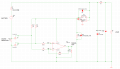
I’m new to this and would appreciate your feedback on the attached circuit. I’m trying to measure bidirectional current—mainly for a rough estimate, but most importantly to confirm the direction of current flow.

I’ve attempted to simulate it in eDSim, which has been a learning experience in itself. Any suggestions or corrections would be highly appreciated!

Thanks in advance, Morten
 

Attachments

crutschow

Joined Mar 14, 2008
38,314
Does the simulation work?

What is the purpose of U1, U3, and R1?
The 10meg resistors seem to serve no useful purpose.

Exactly what output do you expect from this circuit?
 

MisterBill2

Joined Jan 23, 2018
27,159
I am not convinced that you can use the same supply to operate the op-amp that you are monitoring.
AND the whole scheme seems to have more resistors than it needs. What is the purpose of U4??
 

Thread Starter

mortenlund

Joined Mar 20, 2020
29
Does the simulation work?

What is the purpose of U1, U3, and R1?
The 10meg resistors seem to serve no useful purpose.

Exactly what output do you expect from this circuit?
It was a transient analysis and it kind of worked with a 50 times the current over the shunt + the 2.5V. But lots of *convergence errors* and unable to find dc operating point. Might have left some resistors on the circuit diagram that I thought would help the convergence, like the 10meg from the output.
R1 is standin for a 40A fuse. U1 and U3 is suppose to lift the reference so the voltage will swing around 2.5 to be able to measure negative current.

The 12.6 V source is a battery. More batteries is planed to go in parallel. So want to be able to measure if there is a mismatch, eg. one battery is only 12.1V and current will start to flow from the other batteries into that battery. Most important is to see the direction, less important is the precision of how many amps is flowing. But am testing with a proper currentsens amplifier TSC2011 which has internal ref of 2.5V and 60 times amplification. Its a bit pricy though.
 
Last edited:

Thread Starter

mortenlund

Joined Mar 20, 2020
29
I am not convinced that you can use the same supply to operate the op-amp that you are monitoring.
AND the whole scheme seems to have more resistors than it needs. What is the purpose of U4??
I should have pointed out that it is suppose to measure current from the 12.6V battery and more 12.6V batteries is suppose to go in parallel. Each with its own shunt and current sens circuit. The 5V regulator will supply them all. There is also some temp measurement included with a break function.
 

schmitt trigger

Joined Jul 12, 2010
2,027
In addition to all the other comments, how do you expect the opamp’s output to provide a negative voltage without it being powered with a bipolar supply?
Of course, by biasing the opamps inputs mid supply.
But a far, far better solution would be a Hall effect based sensor. Not only it provides bipolar(*) current sensing capability when powered by a single logic level supply, it also provides isolation from the line being sensed.

(*) I know that there are devices that are designed for single polarity sensing, but the majority of available devices are bipolar.
 

MisterBill2

Joined Jan 23, 2018
27,159
WHY the very large resistors around the amplifier IC?? AND, is it actually an IC, or is it a differential amplifier that has separate connections for setting the gain??
 

ronsimpson

Joined Oct 7, 2019
4,645
The two TL431s are going to cause trouble. In spice they will have the same voltage but in real life they will not.
Us a Rail to Rail input and output op-amp. There are many. There are some nice ones that work if the supply is under 6V. Use an op-amp that has a Comon Mode input voltage range that includes the negative supply. Or use a R-R amp. Put a cap on the OP-amp supplies.
I don't understand the many diodes. I removed most. I put a small diode so only plus voltage will go to the regulator. Revers battery protection.
Regulators need input and output caps.
1769042021471.png
 

MisterBill2

Joined Jan 23, 2018
27,159
CERTAINLY Danko, in post#13, has presented what I consider an effective circuit to provide the functionality described in post #1.
If very accurate current readings would be required then adding regulation to the supply for the op-amp and offset divider may be required.
 

Thread Starter

mortenlund

Joined Mar 20, 2020
29
WHY the very large resistors around the amplifier IC?? AND, is it actually an IC, or is it a differential amplifier that has separate connections for setting the gain??
The TSZ121 is an STM op amp with zero drift (chopper). The 10meg is a resistor I forgot to remove.
 

Thread Starter

mortenlund

Joined Mar 20, 2020
29
In addition to all the other comments, how do you expect the opamp’s output to provide a negative voltage without it being powered with a bipolar supply?
Of course, by biasing the opamps inputs mid supply.
But a far, far better solution would be a Hall effect based sensor. Not only it provides bipolar(*) current sensing capability when powered by a single logic level supply, it also provides isolation from the line being sensed.

(*) I know that there are devices that are designed for single polarity sensing, but the majority of available devices are bipolar.
The setup is suppose to be able to distinguish hopefully down to at least 10mA current flow in both directions. Dont think a hall can do that?
 

Thread Starter

mortenlund

Joined Mar 20, 2020
29
The two TL431s are going to cause trouble. In spice they will have the same voltage but in real life they will not.
Us a Rail to Rail input and output op-amp. There are many. There are some nice ones that work if the supply is under 6V. Use an op-amp that has a Comon Mode input voltage range that includes the negative supply. Or use a R-R amp. Put a cap on the OP-amp supplies.
I don't understand the many diodes. I removed most. I put a small diode so only plus voltage will go to the regulator. Revers battery protection.
Regulators need input and output caps.
View attachment 362524
Thank you very much. There is plenty of headroom for protections diodes. This is great.
 
Top