Beginner question on opamp/comparator ic

Thread Starter

etonam

Joined Jun 21, 2016
20
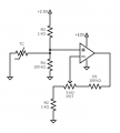
Hi there. I have the schematics attached wired. TC (= thermo-couple) brings 0V in the + input. On - input, I have 0.06V to about 0.6V while output is at about 8.8V ; is there not something wrong? shouldn't the output also be at 0V? The opamp ic is LM833N. I followed datasheet recommendation and grounded the other inputs, leaving the other output open. To my surprise, it didn't measure 0V but fluctuates about 8.5V ; is this not wrong? isn't my chip faulty? Sorry to bother with these beginner questions as I'm just starting out using opamp/comparator ic. Thanks, Etonam.
 

Attachments

WBahn

Joined Mar 31, 2012
32,702
The next thing you need to do is follow the datasheets guidance on the input voltage range. This amp needs the voltage at each input to be as much as 3 V away from the power rails in order to function within spec. Violate that, and all bets are off.
 

MrChips

Joined Oct 2, 2009
34,626
Thermocouple amplifiers are not simple because of the very low voltages and the need for a cold temperature reference.

What are you trying to do?
 

Thread Starter

etonam

Joined Jun 21, 2016
20
@MrChipsThis piece is part of a hot air control circuit.
@WBahn I just went thru the LM833 datasheet again, and I now see that it is not even meant for single supply use !
 

WBahn

Joined Mar 31, 2012
32,702
@WBahn I just went thru the LM833 datasheet again, and I now see that it is not even meant for single supply use !
No, it's not, but all that means is that you need to stay away from the rails. After all, there is no "ground" connection to the chip, so it has no idea whether or not you have a split supply or a single supply.
 

MrChips

Joined Oct 2, 2009
34,626
If you are learning how to measure temperature, there are other devices you can play with, for example, thermistors, and LM34 or LM35.
 

Thread Starter

etonam

Joined Jun 21, 2016
20
@WBahn LM833 has an input CM range of +/- 14V in dual supply. So if I stay within 1V from the pwr rail in single supply, I should be ok? 'the piece' is the circuit base for my topic. It's in my 1st post. It is part of a hot air control circuit. 'the job' is amplifying the thermo-couple voltage.
 

WBahn

Joined Mar 31, 2012
32,702
@WBahn LM833 has an input CM range of +/- 14V in dual supply. So if I stay within 1V from the pwr rail in single supply, I should be ok? 'the piece' is the circuit base for my topic. It's in my 1st post. It is part of a hot air control circuit. 'the job' is amplifying the thermo-couple voltage.
That is the "typical" CM range (for ±15 V supplies). But you shouldn't rely on that -- this would be like relying on someone being average height and weight when designing an amusement park ride. The minimum is ±12 V, which is the spec that the manufacturer guarantees (at least under the specified test conditions).

But before you worry too much about that, I would recommend that you spend some time reading about how to use thermocouples and the recommended circuits for interfacing to them.
 

BobTPH

Joined Jun 5, 2013
11,463
Using an opamp not designed for single supply with a single supply is just plain silly.

There are plenty of single supply opamps with CMR including the rails available today.

So, either use a dual supply, or switch to an appropriate opamp.
 

Thread Starter

etonam

Joined Jun 21, 2016
20
@WBahn I have one more question. I'm also using one comparator on LM393 with a single supply of 10V. Again, as recommended by the datasheet, I grounded the inputs of the other comparator. Its output is left open, when I probe it, it fluctuates around 8.5V instead of 0V. what have I gotten wrong here? Thanks.
 

MrChips

Joined Oct 2, 2009
34,626
Beginner’s mistake. You cannot test a comparator output if the output is left open. Most comparators have what is known as “open collector“ output. The collector at the output transistor is uncommitted. You need to add a pullup resistor from the output to an appropriate positive voltage source. This allows you to interface the comparator to any voltage level.

Edit: It also allows you to connect the outputs of more that one comparators to create a “wired-OR” gate for NEGATIVE LOGIC, or an AND gate.
 

WBahn

Joined Mar 31, 2012
32,702
@WBahn I have one more question. I'm also using one comparator on LM393 with a single supply of 10V. Again, as recommended by the datasheet, I grounded the inputs of the other comparator. Its output is left open, when I probe it, it fluctuates around 8.5V instead of 0V. what have I gotten wrong here? Thanks.
The first question to consider is why you think the output should be at 0 V in the first place?

A comparator like this has a large-signal voltage gain in excess of 100,000, so the difference between the output being driven into saturation versus driven into cutoff is on the order of tens of microvolts.

When you connect both inputs to ground, they are not going to be at exactly the same potential. Which one will be 10 µV higher than the other? No one knows. Even if they are tied together, the difference will be determined by mismatches in offset voltages and currents.

On top of that, the output of this (and most) comparator is open collector. So while it can actively pull the output toward the lower rail, it merely disconnects the output and let's it float in the other direction. You need some kind of pullup to establish the high level output voltage. This is done for a few reasons. Comparators are often used as switches to turn on and turn off light loads directly. It also allows them to be used with different voltage systems in the output circuit, and let's them be used in a "wired-AND" configuration in which the outputs of multiple comparators are tied together and the output is HI only if the outputs of all of the comparators are HI, while it is LO if any of them is LO.
 

Reloadron

Joined Jan 15, 2015
7,850
@MrChips This piece is part of a hot air control circuit. Do you think this piece can do the job?
No and here is why:
Thermocouple amplifiers are not simple because of the very low voltages and the need for a cold temperature reference.

What are you trying to do?
I am not seeing any CJC (Cold Junction Compensation)? While no circuits are provided in this link you will know what CJC actually is and why it's required in TC measurement circuits. Depending on range you need you may want to consider another temperature sensor type. You may also want to consider an off the shelf turn key solution.

Ron
 

sparky 1

Joined Nov 3, 2018
1,218
The AD8494 datasheet shows a thermo couple circuit, it also has a 1M resistor see datasheet. *// a setpoint controller shown p14
It Looks like an intrumentation op amp, A 3 opamp configuration with pnp input but it also has compensation circuit.
These seem simple until you notice what is hiding inside.
AD8494/AD8495/AD8496/AD8497 (Rev. C)
This one is in the older equipment but shows mV table and other artifacts.
AD594/AD595 Data Sheet

You can also search for TL074 configured as instrumentation op amp
The basic idea is to amplify the thermo-couple's tiny uV to mV.
You establish a window of reference values in mV as a set point,
the amplified output of the thermo-couple is compared to this.

An op amp will work at keeping the inverting and non inverting inputs the same.
Unlike a regular op amp, the instrumentation op amp produces a positive error or a negative error.
It can be viewed as heater on, heater off however a control loop and a mosfet can be proportional.
Instead of abruptly turning on and off the action can increase or decrease smoothly so the hot air temperature
remains within the window that you set or the"set point".
 
Last edited:
Top