Sensing Current and Voltage of DC BUS three-phase inverter

Thread Starter

andrew74

Joined Jul 25, 2022
263
Hi again,

From what it looks like, you are using a DC to DC converter to power some load, and you want to measure the input current to the main DC to DC converter right?
If the main DC to DC is isolated and you are using that to power the measurement circuit, then you might need isolation. It despends on how the grounds are connected.

In order for the main DC to DC to be isolated, it would have to be using some kind of transformer.

Also, how fast does the measurement have to be? If it does not have to be superfast there are some really good op amps available for that. I did not check the specs on the one you mentioned yet though does that have low input offset specs?
Yes, something like NCS6S family should isolate
I’d found an AMC0300DDWVR isolated amplifier, but I don’t like the fact that I have to use an additional DC-DC converter to generate 5V for it
 

Thread Starter

andrew74

Joined Jul 25, 2022
263
Hi,

Sorry but you have to at least answer all the questions asked of you or it is impossible to give you advice that is going to help.
You're right! I'd missed that.

1) Yes, I'm sing a DC to DC converter to convert 48V DC bus to 5V, and I want to measure the input current to the main DC to DC converter (so in the 48V). I would like to monitor it for any overcurrents

2) To be honest, I don't usually know the sampling time at which the current on the DC bus of a three-phase inverter is measured, and at this early stage I don't even know the sampling rate of the microcontroller's ADC; unfortunately, I don't have enough data at the moment. I’ve read that the AMC0300DDWVR has a maximum bandwidth of 280 kHz

3) The AMC0300DDWVR has ±0.2mV offset error
 

MrAl

Joined Jun 17, 2014
13,769
You're right! I'd missed that.

1) Yes, I'm sing a DC to DC converter to convert 48V DC bus to 5V, and I want to measure the input current to the main DC to DC converter (so in the 48V). I would like to monitor it for any overcurrents

2) To be honest, I don't usually know the sampling time at which the current on the DC bus of a three-phase inverter is measured, and at this early stage I don't even know the sampling rate of the microcontroller's ADC; unfortunately, I don't have enough data at the moment. I’ve read that the AMC0300DDWVR has a maximum bandwidth of 280 kHz

3) The AMC0300DDWVR has ±0.2mV offset error
Hi,

Ok great.

Now first, does your main converter have an isolated output?
Also, for the 48v to 5v, does it also have to get power from the main converter output?

If the 48v to 5v does not need to be connected to the main 48v converter, you have nothing to worry about. Your secondary system measures the INPUT to the main converter so it can't possibly be isolated. That gives you a lot of freedom.

If I understand this setup right now, you have a 48v main converter call that A and you want to measure the input current.
You also have a secondary converter call that B, and you want to use that to measure that input current.
Now if B does not have to connect to the output of A, you don't need isolation in every case. If it does, then in some cases you need isolation. An example would be if you have to measure the OUTPUT of A as well as the INPUT current to A. You may need isolation if A output is isolated from A input.

There are times when you need isolation and that is usually when something connects to something else that has a different ground potential or is galvanically isolated and you can't afford to violate that state of isolation (with a circuit that connects the input of A to the output of A).

Does this make sense now? We can do another updated diagram if that would help.
 

Thread Starter

andrew74

Joined Jul 25, 2022
263
Hi,

Ok great.

Now first, does your main converter have an isolated output?
Also, for the 48v to 5v, does it also have to get power from the main converter output?

If the 48v to 5v does not need to be connected to the main 48v converter, you have nothing to worry about. Your secondary system measures the INPUT to the main converter so it can't possibly be isolated. That gives you a lot of freedom.

If I understand this setup right now, you have a 48v main converter call that A and you want to measure the input current.
You also have a secondary converter call that B, and you want to use that to measure that input current.
Now if B does not have to connect to the output of A, you don't need isolation in every case. If it does, then in some cases you need isolation. An example would be if you have to measure the OUTPUT of A as well as the INPUT current to A. You may need isolation if A output is isolated from A input.

There are times when you need isolation and that is usually when something connects to something else that has a different ground potential or is galvanically isolated and you can't afford to violate that state of isolation (with a circuit that connects the input of A to the output of A).

Does this make sense now? We can do another updated diagram if that would help.
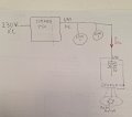
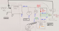
I have attached a high-level block diagram.

The system is complex and consists of many boards and loads; I am interested in the current three-phase inverter PCB used to control the motor. Specifically, I would like to know how to read/monitor the DC bus current.


scheme.jpg


So, the options for isolating the DC bus current measurement are:

- shunt + isolated amplifier (AMC0300DDWVR) .. see the schematic in my post #17 for the "double DC-DC" problem

- Hall sensor like ACS37002LL .. I’m just worried about magnetic interference from the motor windings

- optocoupler(?)
 

MrAl

Joined Jun 17, 2014
13,769
I have attached a high-level block diagram.

The system is complex and consists of many boards and loads; I am interested in the current three-phase inverter PCB used to control the motor. Specifically, I would like to know how to read/monitor the DC bus current.


View attachment 365306


So, the options for isolating the DC bus current measurement are:

- shunt + isolated amplifier (AMC0300DDWVR) .. see the schematic in my post #17 for the "double DC-DC" problem

- Hall sensor like ACS37002LL .. I’m just worried about magnetic interference from the motor windings

- optocoupler(?)
Hello again,

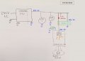
Here is an updated drawing. For this kind of circuit you have to show the grounds because that is the most important thing to consider. You will notice there are three types of grounds in this entire circuit: G1, G2, and G3.

The measuring circuit is shown in the green rectangle. You'll note that it is powered with the 48v buss and it's blue ground. This assumes that ALL the measuring circuits use the same blue ground and you don't need to measure the orange 5v nor the 230vac power line. If you also need to measure either or both of those, then you need isolation which is not shown in the diagram unless you change the shunt to a Hall device or provide some other type of isolation for the measuring circuit.
Also note you have the option to put the measuring circuit in the blue ground lead of the converter that powers the motor instead of the power supply lead. That is shown as the smaller green rectangle. The power would be the same 48vdc and the blue ground.

For the measuring circuit, the Hall device should be ok mounted 9cm from the motor. If you are still that worried though, then use the op amp circuit provided you don't have to measure either of the other two (orange 5v internal, or 230vac).

You will not be measuring the current into Load 1 or Load 2.

See if this all makes sense to you now. See attachment.
 

Attachments

Last edited:

Thread Starter

andrew74

Joined Jul 25, 2022
263
Hello again,

Here is an updated drawing. For this kind of circuit you have to show the grounds because that is the most important thing to consider. You will notice there are three types of grounds in this entire circuit: G1, G2, and G3.

The measuring circuit is shown in the green rectangle. You'll note that it is powered with the 48v buss and it's blue ground. This assumes that ALL the measuring circuits use the same blue ground and you don't need to measure the orange 5v nor the 230vac power line. If you also need to measure either or both of those, then you need isolation which is not shown in the diagram unless you change the shunt to a Hall device or provide some other type of isolation for the measuring circuit.
Also note you have the option to put the measuring circuit in the blue ground lead of the converter that powers the motor instead of the power supply lead. That is shown as the smaller green rectangle. The power would be the same 48vdc and the blue ground.

For the measuring circuit, the Hall device should be ok mounted 9cm from the motor. If you are still that worried though, then use the op amp circuit provided you don't have to measure either of the other two (orange 5v internal, or 230vac).

You will not be measuring the current into Load 1 or Load 2.

See if this all makes sense to you now. See attachment.
Hello, and thank you for your reply :)

1) The green rectangle you’ve drawn is a non-isolated operational amplifier, isn’t it?
If the answer is yes and I wanted to isolate it, how would the schematic change? Do you agree with me that I’d need an additional DC-DC converter? (which isn’t necessary with a Hall sensor)

2) Why exactly 9cm?
 
Last edited:

MrAl

Joined Jun 17, 2014
13,769
Hello, and thank you for your reply :)

1) The green rectangle you’ve drawn is a non-isolated operational amplifier, isn’t it?
If the answer is yes and I wanted to isolate it, how would the schematic change? Do you agree with me that I’d need an additional DC-DC converter? (which isn’t necessary with a Hall sensor)

2) Why exactly 9cm?
Hi,

First I have to ask, why do you need the current measurement isolated? Is it because you intend to run it to a computer or something?

If you use an op amp as you thought and then isolate the output, you might be able to use an analog opto coupler and isolated 5vdc supply.
An alternate would be to use a small 8 pin microcontroller to measure the output, then digitize the measurement and send it via a regular opto coupler to the computer. You can even use the RS232 port then if you have one. In any case, whatever receives the opto output has to use the same protocol as the digitizer. This is an extremely reliable way to achieve isolation, and the isolation is as good as a standard opto coupler. The only care is to keep the opto coupler LED current lower than the max, like shoot for 5ma for a 20ma LED, which ensures long life. Total cost for the digitizer uC chip is under $2.00 USD.

9cm because I think that's good enough when you say it has to be closer than 10cm. You dont want to use 1cm, 2cm, etc., and the max is 10cm, so 9cm should work. Of course you have to test, but if you can run the motor then you can test it. That would be with a decent Hall sensor.

Come to think of it, I also did a digitizer uC for current measurement of a solar panel mounted on an automobile. It would send the digital data wirelessly to the house where it could be detected and decoded and displayed. I also used an LM358 op amp with a little input offset bias help. The shunt value did not have to be super low though because the max current was maybe a little over 1 amp.
 

Thread Starter

andrew74

Joined Jul 25, 2022
263
Hi,

First I have to ask, why do you need the current measurement isolated? Is it because you intend to run it to a computer or something?

If you use an op amp as you thought and then isolate the output, you might be able to use an analog opto coupler and isolated 5vdc supply.
An alternate would be to use a small 8 pin microcontroller to measure the output, then digitize the measurement and send it via a regular opto coupler to the computer. You can even use the RS232 port then if you have one. In any case, whatever receives the opto output has to use the same protocol as the digitizer. This is an extremely reliable way to achieve isolation, and the isolation is as good as a standard opto coupler. The only care is to keep the opto coupler LED current lower than the max, like shoot for 5ma for a 20ma LED, which ensures long life. Total cost for the digitizer uC chip is under $2.00 USD.

9cm because I think that's good enough when you say it has to be closer than 10cm. You dont want to use 1cm, 2cm, etc., and the max is 10cm, so 9cm should work. Of course you have to test, but if you can run the motor then you can test it. That would be with a decent Hall sensor.

Come to think of it, I also did a digitizer uC for current measurement of a solar panel mounted on an automobile. It would send the digital data wirelessly to the house where it could be detected and decoded and displayed. I also used an LM358 op amp with a little input offset bias help. The shunt value did not have to be super low though because the max current was maybe a little over 1 amp.
Hi!

I want to isolate the current measurement because, in the event of a fault, interference or malfunction on the 48V supply, I don’t want it to affect the rest of the machine (which operates on the same 48V supply).

So you mean I have an isolated DC-DC converter that converts 48V to 5V_A .. and then an analogue optocoupler that takes 5V_A and "create" 5V_B isolated.
These 5V_B will supply my isolated op-amp? (like AMC0300)
Have I got that right?

If the answer is yes, I have a concern: an op-amp consumes power, and a photocoupler is designed to transmit a light signal, not to transfer energy; therefore, the current output from the photocoupler is too weak to power the internal circuits of an isolated op-amp.
 

MrAl

Joined Jun 17, 2014
13,769
Hi!

I want to isolate the current measurement because, in the event of a fault, interference or malfunction on the 48V supply, I don’t want it to affect the rest of the machine (which operates on the same 48V supply).

So you mean I have an isolated DC-DC converter that converts 48V to 5V_A .. and then an analogue optocoupler that takes 5V_A and "create" 5V_B isolated.
These 5V_B will supply my isolated op-amp? (like AMC0300)
Have I got that right?

If the answer is yes, I have a concern: an op-amp consumes power, and a photocoupler is designed to transmit a light signal, not to transfer energy; therefore, the current output from the photocoupler is too weak to power the internal circuits of an isolated op-amp.
Hi,

Oh ha ha, yes that would probably not power much I don't think.

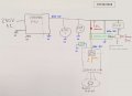
(See new drawing in attachment)

The idea is this:
Use the raw 48v supply to power the op amp circuit, the op amp will have a single output Vout referenced to ground GND. So you have Vout and GND that are not isolated.
Solution A: You run Vout and GND to an analog opto isolator (not a opto coupler). The input comes from the non isolated op amp circuit output and ground. The output of the opto isolator goes to a new circuit that runs off of an isolated 5v supply (48v to 5v isolated). That output circuit is completely isolated.

Solution B: You do the same thing with the op amp circuit, but run the output of the op amp to a microcontroller. The microcontroller drives a regular opto coupler (not an analog isolator). The output of the opto is isolated, you use that with the 48v to 5v isolated supply to power the display or whatever.

I don't understand your first line. You say you do not want the "rest of the circuit" to be affected, but it already runs from the same 48v supply isolated or not isolated. So how do you expect the "rest of the circuit" to work if the 48v supply goes away for some reason? If 48v powers the isolated 5v supply, that 5v supply goes dead as well as the 48v supply. You'd need a separate 48v supply to power the display or whatever if you didn't want it to go dead as well.
Does that make sense to you?
 

Attachments

Last edited:

panic mode

Joined Oct 10, 2011
5,181
also i like to have my controls/display etc working no matter what (blown F2 fuse, tripped some interlock, safety circuit, overload, whatever).
therefore i would rather use AC/DC dedicated PSU for controls. then you can have diagnostics etc. rather than dark screen.

any circuit on the load side can be obtaining power from the control side. no need to derive power from dirty load circuit (48VDC),
just use small cheap DCDC isolated converters like B0505S (1W, 3W, whatever you need) to power your sensing or IO in the dirty zone.
there are tons of IO options that can run on 5V on that dirty side, all you need to use is an signal isolator (like I2C isolator) so, you don't need to handle isolation signal, by signal and in analog domain. you can have an entire ecosystem there, with ADCs of whatever resolution you choose to use

1775490988546.png
 
Last edited:

panic mode

Joined Oct 10, 2011
5,181
btw, post #2 proposed ACS7xx series product. later on i saw post stating that current is up to 5A.

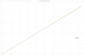
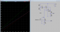
if you are looking for isolation and an analog output, they are excellent choice. you can get ready modules from Amazon to try out.since your current is 0-5A and always in one direction, i would recommend something like ACS724LLCTR-05AU-T (0-5A). Or ACS724LLCTR-10AU-T (0-10A) if you prefer wider range. they are very well behaved, reliable and output is linear. here are some graphs comparing several units with 10A chip, yellow one is not yet trimmed, though still pretty close.
1775521796890.png

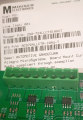
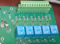
just populated one more channel on few boards with 10 version, did not clean it yet...

1775518380897.png
just keep in mind that output is voltage signals 0.5V.. 4.5V (values correspond to min and max current). for mentioned chips, 0.5V output means zero current, and 4.5V means max current (5 or 10 or 20A depending on chip).

there are also bi-directional parts. their output is at 0.5V for max negative current, and 4.5V for max positive current.

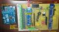
if you are looking at digital sensor, things like INA226 (16-bit current and voltage sensor) or newer INA228 (20-bit) come to mind. they have I2C interface but they are not isolated and need shunt. this is kind of devices one would use with what I2C isolator (another IC, like ADUM1201 for example) and small DC/DC converter like B0505S-1W.

just got me some INA228 chips. will swap one on INA226 module (pin compatible, code will be different).
much easier to experiment on a little test bed like this then developing upgrading real products like in last image.
1775520573423.png
1775565413744.png
 
Last edited:

Thread Starter

andrew74

Joined Jul 25, 2022
263
btw, post #2 proposed ACS7xx series product. later on i saw post stating that current is up to 5A.

if you are looking for isolation and an analog output, they are excellent choice. you can get ready modules from Amazon to try out.since your current is 0-5A and always in one direction, i would recommend something like ACS724LLCTR-05AU-T (0-5A). Or ACS724LLCTR-10AU-T (0-10A) if you prefer wider range. they are very well behaved, reliable and output is linear. here are some graphs comparing several units with 10A chip, yellow one is not yet trimmed, though still pretty close.
View attachment 365673

just populated one more channel on few boards with 10 version, did not clean it yet...

View attachment 365669
just keep in mind that output is voltage signals 0.5V.. 4.5V (values correspond to min and max current). for mentioned chips, 0.5V output means zero current, and 4.5V means max current (5 or 10 or 20A depending on chip).

there are also bi-directional parts. their output is at 0.5V for max negative current, and 4.5V for max positive current.

if you are looking at digital sensor, things like INA226 (16-bit current and voltage sensor) or newer INA228 (20-bit) come to mind. they have I2C interface but they are not isolated and need shunt. this is kind of devices one would use with what I2C isolator (another IC, like ADUM1201 for example) and small DC/DC converter like B0505S-1W.

just got me some INA228 chips. will swap one on INA226 module (pin compatible, code will be different).
much easier to experiment on a little test bed like this then developing upgrading real products like in last image.
View attachment 365670
View attachment 365672
Hi,

Oh ha ha, yes that would probably not power much I don't think.

(See new drawing in attachment)

The idea is this:
Use the raw 48v supply to power the op amp circuit, the op amp will have a single output Vout referenced to ground GND. So you have Vout and GND that are not isolated.
Solution A: You run Vout and GND to an analog opto isolator (not a opto coupler). The input comes from the non isolated op amp circuit output and ground. The output of the opto isolator goes to a new circuit that runs off of an isolated 5v supply (48v to 5v isolated). That output circuit is completely isolated.

Solution B: You do the same thing with the op amp circuit, but run the output of the op amp to a microcontroller. The microcontroller drives a regular opto coupler (not an analog isolator). The output of the opto is isolated, you use that with the 48v to 5v isolated supply to power the display or whatever.

I don't understand your first line. You say you do not want the "rest of the circuit" to be affected, but it already runs from the same 48v supply isolated or not isolated. So how do you expect the "rest of the circuit" to work if the 48v supply goes away for some reason? If 48v powers the isolated 5v supply, that 5v supply goes dead as well as the 48v supply. You'd need a separate 48v supply to power the display or whatever if you didn't want it to go dead as well.
Does that make sense to you?
Hello, and thank you for your detailed replies :)

-----------------------------------------------1° QUESTION (about the layout)--------------------------------------------------------------
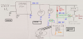
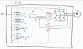
I’m not 100% sure I’ve understood the final circuit ‘layout’, so I’ve redrawn it to clearly show that I need everything on a single PCB (whereas in the photo you attached in post #32, it looks as though there are several separate PCBs).

As I said, I want a three-phase motor driver that isolates the 48V from the microcontroller and the low-level logic (5V and 3V).

SmartSelect_20260407_092449_Squid.jpg

Let’s not focus on the choice of components for now (which DC-DC converter is best, which amplifier, etc.), but on the overall layout.
..for example for voltage sensing I drawn the AMC1311 but solutions such as the INA228 that you recommended might be much better (with the following I2C isolator)

@MrAi Sorry, but your two solutions, A and B, aren’t very clear to me; I’d need to try and sketch them out to understand (which I will do shortly).

What do you think of the circuit I’ve drawn?
At first, I didn’t want to use two isolated DC-DC converters because I thought they were all as large and bulky as the NCS6S4805, which would have taken up too much space..
But now I found some compact isolated solutions online, such as the TRACO TRN 1-48-11, which I could use just to power the op-amps (here we should ask ourselves whether its "low output wattage" is sufficient).
For everything else on the pcb I use the NCS6S4805 with its 5-6W.
I think this is the ‘simplest’ solution, and cost isn’t an issue.
What do you think?


----------------------------------------------2° QUESTION (about the components choice)------------------------------------------------
Let's assume I use ACS724LLCTR-10AU-T (0-10A) ... it produces [0,5 ... 4,5]V output that I need to send to a Texas Instruments C2000 microcontroller, which has a standard input range of 0 V to 3.3 V.

Do you agree with me that I should implement one of these:
- Resistive voltage divider: a step-down ratio of approximately 0.66 should convert the 4.5 V to approximately 3 V protecting the microcontroller pin
- Buffer with Op-Amp: a 3.3V op-amp in a buffer configuration with an input voltage divider that sould also 'clip' any dangerous spikes above 3.3 V


Thank you.
 
Last edited:

panic mode

Joined Oct 10, 2011
5,181
the layout you meant according to what i understand (BLDC current is to be measured either on high or low side, rather than one of phases):
1775563528074.png


the other thing is that Traco TRN1-4811 is same size but costs 5x more than more common 5V alternatives like B0505S.
using 5V variant would look the same but the input side is not 48VDC, it is 5V from +5V_A.

about ACS7xxx output scaling:
one could use voltage divider... a bit is lost due gap on low side which is not a big deal.

i chose to use opAmp to translate 0.5-4.5V to standard 0-5V. this is easily adapted to anything else including 0-3.3V... or keep it as is and simply add voltage divider.
this way opAmp can never get higher than 5V and divider will ensure STM never sees more than 3.3V.

but... since in this case circuit is not entirely analog, things are easier, so using voltage divider should be fine. 10% of range is easily compensated by 1 more bit in ADC or oversampling.
1775567695007.png
 
Last edited:

Thread Starter

andrew74

Joined Jul 25, 2022
263
the other thing is that Traco TRN1-4811 is same size but costs 5x more than more common 5V alternatives like B0505S
Yes, but the Traco TRN1-4811 converts 48V to 5V, whereas the B0505S converts 5V to 5V
In the circuit layout I suggested in my previous #34 reply, I use two DC-DC converters "in parallel" (obviously they're not) to step down 48V to 5V... perhaps you’re thinking of connecting the B0505S in series after the NCS6S4805C?
 
Last edited:

Thread Starter

andrew74

Joined Jul 25, 2022
263
BLDC current is to be measured either on high or low side, rather than one of phases
The measurement is more accurate when taken using a shunt connected directly to the motor phases, as it is a ‘direct’ measurement of the load rather than a kind of reconstruction, as is the case with a shunt connected to the source of the low-side MOSFET
 

panic mode

Joined Oct 10, 2011
5,181
you know the best what works for you and your application requirements.

my experience is with industrial equipment and i stated in #32 why i would use different way to derive power.

similarly measuring motor phases is more direct. but... it also matters what are you trying to do with it.
 

MrAl

Joined Jun 17, 2014
13,769
btw, post #2 proposed ACS7xx series product. later on i saw post stating that current is up to 5A.

if you are looking for isolation and an analog output, they are excellent choice. you can get ready modules from Amazon to try out.since your current is 0-5A and always in one direction, i would recommend something like ACS724LLCTR-05AU-T (0-5A). Or ACS724LLCTR-10AU-T (0-10A) if you prefer wider range. they are very well behaved, reliable and output is linear. here are some graphs comparing several units with 10A chip, yellow one is not yet trimmed, though still pretty close.
View attachment 365673

just populated one more channel on few boards with 10 version, did not clean it yet...

View attachment 365669
just keep in mind that output is voltage signals 0.5V.. 4.5V (values correspond to min and max current). for mentioned chips, 0.5V output means zero current, and 4.5V means max current (5 or 10 or 20A depending on chip).

there are also bi-directional parts. their output is at 0.5V for max negative current, and 4.5V for max positive current.

if you are looking at digital sensor, things like INA226 (16-bit current and voltage sensor) or newer INA228 (20-bit) come to mind. they have I2C interface but they are not isolated and need shunt. this is kind of devices one would use with what I2C isolator (another IC, like ADUM1201 for example) and small DC/DC converter like B0505S-1W.

just got me some INA228 chips. will swap one on INA226 module (pin compatible, code will be different).
much easier to experiment on a little test bed like this then developing upgrading real products like in last image.
View attachment 365670
View attachment 365691
That 14 bit ADC Arduino Uno looks very interesting. It also has 12 bit DAC from what I've read now.
I'd get one but not sure I will have the time to play with it as I have so many things going on already I can hardly get to.
 
Last edited:

MrAl

Joined Jun 17, 2014
13,769
the layout you meant according to what i understand (BLDC current is to be measured either on high or low side, rather than one of phases):
View attachment 365686


the other thing is that Traco TRN1-4811 is same size but costs 5x more than more common 5V alternatives like B0505S.
using 5V variant would look the same but the input side is not 48VDC, it is 5V from +5V_A.

about ACS7xxx output scaling:
one could use voltage divider... a bit is lost due gap on low side which is not a big deal.

i chose to use opAmp to translate 0.5-4.5V to standard 0-5V. this is easily adapted to anything else including 0-3.3V... or keep it as is and simply add voltage divider.
this way opAmp can never get higher than 5V and divider will ensure STM never sees more than 3.3V.

but... since in this case circuit is not entirely analog, things are easier, so using voltage divider should be fine. 10% of range is easily compensated by 1 more bit in ADC or oversampling.
View attachment 365696
Hello,

You seem to have changed a lot of things here. You are also measuring current in a different place.

The short answer is that if a circuit does not share the very same ground as the other grounds, then it has to be isolated (in most cases).
There are two basic ways to isolate:
1. Use an analog isolator IC to convert the output of any op amp to another circuit with isolation, when that other circuit has to also have an isolated DC supply like a DC to DC isolated converter.
2. Use a microcontroller to generate pulses that conform to some digital standard like 16 bit binary, or even a set of BCD digits with ASCII encoding.

I'm not sure what to draw now because you do not seem to understand the drawings when they are very clear. Just remember, an isolated DC supply and isolate any output from an op amp using 1 or 2 above. That should get you there. You could look at each current measurement as a completely separate circuit with a separate DC supply and isolator of either type 1 or 2 above.

Does that help?
 
Top