Facebook
 Google
 GitHub
 Linkedin
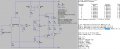
I'm pretty shocked... So detaching the feedback loop as I did, connecting the negative input to ground and doing the AC analisis of the point that has been detached don't give me loop gain (A*beta), right?The method you used to find the loop gain is completely wrong.
I'm sorry to bother you but since english is not my first language (as you may have understood) I just want to be sure to have understood correctly.
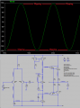
when you talk about the unity gain, do you refer to the closed loop gain?
Maybe all the feedback current of the feedback goes to the negative input of the differential pair and it gives a better performance? mmmh maybe it's not the case since the input stage is a transconductance amplifier (voltage in current out) right? well... I don't know...How this capacitor affects the amplifier voltage gain (ACL)?