Three stages power amplifier school project

Thread Starter

Lucky-Luka

Joined Mar 28, 2019
181
ronsimpson
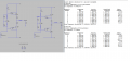
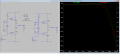
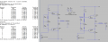
I've tried your circuit. Have I done something wrong or with a 175 mV input I don't get a 14V output as expected? It's possible that I wasn't clear in the assignment at the beginning...
 

Jony130

Joined Feb 17, 2009
5,598
But why you want to see this 15mA?

I thought that grounding the input would give me those 15mA.
But notice that you also have a load resistance. That will affect the circuit DC operating point too.
Because the PNP base is at 0V now the output voltage is no now longer equal to 0V (we have a positive voltage at the output). So, the current must flow through this load resistance and this current will be provided by NPN transistor. Hence NPN will conduct more current and the PNP will conduct less current.
 

ronsimpson

Joined Oct 7, 2019
4,702
Here is a modif
It's possible that I wasn't clear in the assignment at the beginning...
The assignment if for you to do. I am just having fun and trying to help you learn. The gain is in post #43. Something you need to know.
Just for education, not for your assignment, Here is a different type of output stage. It has only one B-E offset not two for each transistor pair. Note the voltage across Q5 is 1/2 as much.
1577146549086.png
 

Attachments

Thread Starter

Lucky-Luka

Joined Mar 28, 2019
181
Do you think Sziklai is a better configuration?

Let's assume that I adopt that configuration for the project. I'm trying to build stage after stage looking at your example in order to understand the circuit better.
I've noticed that with a 14V input in the last stage I got less that 14V sweep at the output. Isn't it a follow emitter stage? It cannot be due only to R2 and R5. There must be something else that I don't understand.

How can I choose the current generator value? It has to be more than the maximum Q2 base current and it has to polarize Q5. I've tried with 10mA and it seems to work just fine. Is there a rule of thumb?
Thanks
 

Attachments

Audioguru again

Joined Oct 21, 2019
6,826
You do not understand that Q2 and Q4 are emitter-followers with a Vbe of about 0.7V each, plus the saturated Vce of Q3 and Q1 which might be 0.3V each.
Also, the 13.3V across the 10 ohms load causes a current of 0.625V in R2 and R5.

We do not know the voltage loss of the current source and current sink. The simulation seems to ignore a voltage loss.
We also do not know if the output is clipping since your timebase shows 10 skinny sinewaves instead of clearly showing only 2 sinewaves that are wide enough to see clipping.
 

ronsimpson

Joined Oct 7, 2019
4,702
Do you think Sziklai is a better configuration?
I wanted you to know there are more than one way to make a output stage.
It is very hard to make a output stage that will output 14V on a 16V supply. Probably more than most students can do.
I think the Sziklai will work better if you need to get to 14V output with out distortion. Tell me why this is true? Your teacher may ask you. Have you looked at the bandwidth?
What school are you in?
Look at post #1. Do you have the input impedance set to 10k? What is the open loop gain?
 

Attachments

Thread Starter

Lucky-Luka

Joined Mar 28, 2019
181
I think the Sziklai will work better if you need to get to 14V output with out distortion. Tell me why this is true? Your teacher may ask you. Have you looked at the bandwidth?
I have read in several places that it is like that but I haven't really uderstood why (even because it wasn't mentioned). Can you tell me why it is more linear please?
LTSpice confirms this fact too: I have looked at the THD and bandwidth.... I hope I've done it in the right way...
The badwidth looks like the Sziklai configuration performs a little better.

Look at post #1. Do you have the input impedance set to 10k? What is the open loop gain?
The input impedence should be greater than 10k.
 

Attachments

Audioguru again

Joined Oct 21, 2019
6,826
Your numbers are for a simulation that might be wrong. A real circuit might produce completely different amounts of distortion. You do not even have a complete amplifier with plenty of open-loop gain and lots of negative feedback.
 

Thread Starter

Lucky-Luka

Joined Mar 28, 2019
181
After the output stage (it should be ok... ) I've tried to add the gain stage. Epic fail. I've tried giving it Ib=Ic/beta. Ic has the value I found in the schematic without the CE stage . Biasing is gone. I couldn't get the right ccollector voltage of Q2. What's the method to progress?
Thanks
 

Attachments

Audioguru again

Joined Oct 21, 2019
6,826
The text on your schematics is too small to be seen because the parts are too far apart.
The distortion on the waveform cannot be seen because the timebase is too long and it shows too many skinny sinewaves.

The gain schematic shows -6VDC on the speaker which is very bad. It should be very close to 0VDC.
 

Ylli

Joined Nov 13, 2015
1,092
After the output stage (it should be ok... ) I've tried to add the gain stage. Epic fail. I've tried giving it Ib=Ic/beta. Ic has the value I found in the schematic without the CE stage . Biasing is gone. I couldn't get the right ccollector voltage of Q2. What's the method to progress?
Thanks
I gave you a new bias value on your thread in another forum . Try 25.6144 uA.
 
Last edited:

Ylli

Joined Nov 13, 2015
1,092
With the bias offset as far as it was, I think you may be seeing a combination of crossover distortion and clipping. Remember, that when you get the input stage connected, and feedback enabled to set the closed loop gain, the output will nominally bias itself to 0 volts. Oh, and I determined that 25.6144 uA via trial and error.
 

Thread Starter

Lucky-Luka

Joined Mar 28, 2019
181
Oh, I think I understand. Can you even tell me the relations you adopted to obtain that current value? IC=Ib/beta alone isn't enough, right?
 

Ylli

Joined Nov 13, 2015
1,092
Oh, I think I understand. Can you even tell me the relations you adopted to obtain that current value? IC=Ib/beta alone isn't enough, right?
Ib = Ic/beta is correct, but the number you see in the LTspice model for BF is valid only at very specific conditions. Ib = Ic/beta will get you in the ball park, but you still need to tweak to find a more exact value. I actually told LTspice to .step the parameter and let it find the optimum value for me, but you can do it manually via trial and error.
 

Audioguru again

Joined Oct 21, 2019
6,826
IC= Ibxbeta only if you measure the beta. But beta for a certain transistor part number is a range of numbers because some transistors have low beta and others have high beta even if they are made by the same manufacturer. When you buy a transistor you do not know its actual beta. That is why a transistor must be biased with a voltage divider and an emitter resistor to reduce the bad effects of beta variance.
 
Top