Three stages power amplifier school project

Thread Starter

Lucky-Luka

Joined Mar 28, 2019
181
Why does every school project here have a student without a text book and without a teacher??
That's the point.
I do have books (Sedra/Smith and Razavi). I don't have the time to read them thoroughly since other exams keep copming, one after the other... It's like a war against time.
Regarding the teacher's work I prefer not to speak.
I just try my best...

I played with Q5 B-C resistor and the output transistor Emitter resistors.
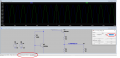
The red trace in for one transistor and the green trace is current in the other transistor. Blue is output voltage.
Note at zero voltage out the current in each transistor is 100mA. This could be set with the input signal=0V.
I used chose 1.6 watts in each transistor when nothing is happening. (lost power but needed)
Both transistors need to be a little bit on at 0V or there will be cross over distortion. (bump in the signal at 0V)
Whoa! Thanks for the circuit suggested.
Do you think I can get even less than 100 mA in the output transistors at 0 voltage out? I think that in such a way the distorsion increases, right?
Do you think that I can get rid of R11?
Why did you put C1 in the retroaction?
What is R12 at the input for?
Thanks a lot

By measuring the quiescent current in the output transistors.
It's less than 0.65*4 (my initial thought) because not all 4 darlington transistors are full power at the same time, right?
 

Audioguru again

Joined Oct 21, 2019
6,690
Lucky-Luka, did you notice in posts #12 and #19 that the output transistors are not darlingtons with 4 base-emitters in series but instead they are Sziklai pairs (look in Google) that have only 2 base-emitters in series?
 

Thread Starter

Lucky-Luka

Joined Mar 28, 2019
181
Lucky-Luka, did you notice in posts #12 and #19 that the output transistors are not darlingtons with 4 base-emitters in series but instead they are Sziklai pairs (look in Google) that have only 2 base-emitters in series?
Is this reply related to the voltage value at the end of the Vbe multiplier?
 

Thread Starter

Lucky-Luka

Joined Mar 28, 2019
181
I was looking at the circuit AlbertHall posted in his #10 post.
It is written that the quiescent current is 15 mA but in the graph I see near zero value for the same current. Shouldn't the small signal sit onto the biasing value?
I don't quite understand this concept...
 

Attachments

Jony130

Joined Feb 17, 2009
5,488
The quiescent current is 15 mA only when Vin = 0V and both BJT's are ON (Class A). But for positive voltage at the input NPN will start to conduct more current. But at the same time, PNP will start to decrease his current. And at the time when IL = 2 * Iq = 30mA, the PNP will be completely off. And only NPN will provide the current onto the load (Class B).
https://forum.allaboutcircuits.com/...ed-on-push-pull-amplifier.101749/#post-766570
 

ronsimpson

Joined Oct 7, 2019
3,037
It is written that the quiescent current is 15 mA
I think it is a little hard to hit 15mA. Over temperature it will change. Just saying it seems small to me.
I don't really know what value to use. It is a trade off of distortion vs power loss.
I can not find a answer on the internet and my audio amp design books are in my office.
Several sources say to set the quiescent current just to the point where crossover distortion can not be seen on a scope.
 

Thread Starter

Lucky-Luka

Joined Mar 28, 2019
181
I think it is a little hard to hit 15mA. Over temperature it will change. Just saying it seems small to me.
I don't really know what value to use. It is a trade off of distortion vs power loss.
I can not find a answer on the internet and my audio amp design books are in my office.
Several sources say to set the quiescent current just to the point where crossover distortion can not be seen on a scope.
I have tried to replicate your circuit... Something went wrong. There must be an error but I can't see where it is.
 

Attachments

Jony130

Joined Feb 17, 2009
5,488

Thread Starter

Lucky-Luka

Joined Mar 28, 2019
181
Now I'm more confused...
I've tried to ground the input as Jony130 said.
I get 87mA... not 15mA...
What's going on?
Is the DC point mentioned in spice wrong?
 

Attachments

ronsimpson

Joined Oct 7, 2019
3,037
The point you chose to ground is not right. It is about 0.9V away from "Vo". Just like grounding the Base of Q2 is also about 1 volt away form Vo. The voltage from B to E varies with load current. (and temperature)
1577143508393.png
 

Thread Starter

Lucky-Luka

Joined Mar 28, 2019
181
Everything is alright and stop blaming the LTspice. Notice that when Vin = 0V the V4 DC voltage is equal to -1V.
ehm.. I've never blamed LTSpice... just questions... And i'm grateful for all the answers...
But... I haven't understood... sorry.
 

Thread Starter

Lucky-Luka

Joined Mar 28, 2019
181
When you said "The quiescent current is 15 mA only when Vin = 0V and both BJT's are ON (Class A)." I thought that grounding the input would give me those 15mA.
I haven't considered the fact that Vin has to be 0V as Vo has to be 0V.
Maybe I'm starting to undertand what you said before.
 
Top