This circuit to gerber file

Thread Starter

christiannielsen

Joined Jun 30, 2019
381
Hi,

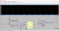
I have this circuit drawn in KiCad.

I need to prepare this for a gerber file.

You might see and know what I need to change and check before I move to the PBC layot Editor. Please let me know.

But I do have the questions:
1. What do I search for in the library to place pin holes for servo and power?
2. How do I change the 4001 to a IC (with power connections)?
 

Attachments

Irving

Joined Jan 30, 2016
3,845
Servo & Power, use generic 1 x 3 and 1 x 2 connector and choose appropriate footprint for pin header.

4001, if you go to its symbol you'll see A,B,C,D gates and E for power pins.

Interesting mix of analogue & digital, whats it for?
 

bertus

Joined Apr 5, 2008
22,270
Hello,

I also think there is a connection failure at C1.
It is not only connected to pin 5, but also to pin 2 and 6 of the 555.
The dot on the crossing should be removed.

Bertus
 

Irving

Joined Jan 30, 2016
3,845
Also C1 & C4 different values, why?
C5 not connected.
As an aside, for decoupling capacitors, eg C5, C6, C7, its better to use the Gnd symbol at the ground end rather than clutter schematic with additional lines crossing the real detail.
 

Thread Starter

christiannielsen

Joined Jun 30, 2019
381
Servo & Power, use generic 1 x 3 and 1 x 2 connector and choose appropriate footprint for pin header.

4001, if you go to its symbol you'll see A,B,C,D gates and E for power pins.

Interesting mix of analogue & digital, whats it for?
Thanks. What do you mean by "appropiate footprint for pin header"?

4001-> There. I see it. So I simply place the "E" part of the 4001 in the diagram?

Its for a Santa Jumping Jack.

Also C1 & C4 different values, why?
C5 not connected.
As an aside, for decoupling capacitors, eg C5, C6, C7, its better to use the Gnd symbol at the ground end rather than clutter schematic with additional lines crossing the real detail.
C1 & C4 -> I dont know. Because it has different functions? :)

I've made the changes you pointed out. Please let me know if I missed something.
 

Attachments

Irving

Joined Jan 30, 2016
3,845
Extraneous wires/joints on U2, U3 and J1 ground.

U2 Q6 to U4A pin 1. Understand what you meant, but KiCad will treat these as different Nets - they should have same, meaningful, name, e.g. STOP ?

+6v to both pins 2 and 3 of Q4, think you don't want link on pin 2.

C1, C4 on NE555 are just bypass caps. 10nF ceramic close to chip; always try to reduce different # of values in circuit.

Maybe I'm going blind, but don't see Q4E or its decoupling capacitor.

I'm guessing this controls up and down movement of puppet in box, by varying duty cycle and therefore speed/direction. 2 different settings. What happens when servo hits limits?

Have you breadboarded this?
 

Thread Starter

christiannielsen

Joined Jun 30, 2019
381
Will all "+6v power ports" automatically be connected?

C1, C4 on NE555 are just bypass caps. 10nF ceramic close to chip; always try to reduce different # of values in circuit.
Okay. Thanks. How will we know which cap we are talking about then?

Maybe I'm going blind, but don't see Q4E or its decoupling capacitor.
I'm not sure what you mean by that. What is Q4E?

I'm guessing this controls up and down movement of puppet in box, by varying duty cycle and therefore speed/direction. 2 different settings. What happens when servo hits limits?
It shouldnt hit limit because I limit the movement by adjusting P1 and P2

Yes I have it on breadboad. Granted. It is a bit unstable at times but Im afraid its the best I can do for now.
 

Irving

Joined Jan 30, 2016
3,845
Will all "+6v power ports" automatically be connected?
Yes, all nets with same name are treated as one

Okay. Thanks. How will we know which cap we are talking about then?
Because one is labelled C1 and the other C4, they just have the same value, 10nF. Incidentally I see you used 103, 104 as the value, but else where you've used 100u, 100n etc. For consistency you should change 103 and 104 to 10n. Also applies to value of C3.

I'm not sure what you mean by that. What is Q4E?
The power pins for U4, sorry I said Q4 doh!

It shouldnt hit limit because I limit the movement by adjusting P1 and P2

Yes I have it on breadboad. Granted. It is a bit unstable at times but Im afraid its the best I can do for now.
Ok. Are you going to make a PCB or just use the layout to guide a stripboard version?
 
Last edited:

Audioguru again

Joined Oct 21, 2019
6,674
R5 and R6 are in parallel, you need only one of them.
The 4001 and the Mosfet do nothing because the Mosfet has +6V on 2 of its 3 pins.
How will you disable the two unused gates in the 4001?
 

Irving

Joined Jan 30, 2016
3,845
Q3 is redundant too. You can connect the output of U3 directly to servo input.

You may find the circuit more stable if you replaced P1 and P2 with 10k trimmers, made R3 1k, R4 270k and C3 100n, and replaced D7 with a small signal Schottky diode. That selection increases the charging/discharge currents in the RC networks and tightens up the switching voltage. Because the currents are so small (2v across 2.7M = 0.7uA) servo noise, mains hum and switching spikes from the other devices could all contribute to variations in the timing.
 

Thread Starter

christiannielsen

Joined Jun 30, 2019
381
Q3 is redundant too. You can connect the output of U3 directly to servo input.

You may find the circuit more stable if you replaced P1 and P2 with 10k trimmers, made R3 1k, R4 270k and C3 100n, and replaced D7 with a small signal Schottky diode. That selection increases the charging/discharge currents in the RC networks and tightens up the switching voltage. Because the currents are so small (2v across 2.7M = 0.7uA) servo noise, mains hum and switching spikes from the other devices could all contribute to variations in the timing.
thanks
R3-4 pre-determines the position of the servo.
P1-2 lets me adjust the two positions of the servo.

The servo i toogling between two positions: 0 and 180 degrees when p1-2 is adjusted.
 

Irving

Joined Jan 30, 2016
3,845
Exactly so. R4 C3 gives you the 20mS pulse rate, but with 2.7M/10nF its quite susceptible to noise. likewise (P1 + R3) C3 gives you one position, (P2 + R3) C3 gives the other. With C3 10nF then again P1/P2 are have to be large pots to give the range also with tiny currents. The result is your trigger point is likely to be quite variable, a few mV of noise on the power lines could shift timing. Now a PCB with a good solid ground plane will improve that, but increasing the charging/discharging currents will improve it more.

Here's a revised element from Q1/Q2 through to your servo output, using the same numbering scheme as your schematic with the addition of R7 . I've also suggested putting some additional decoupling capacitors (C9/C10) by the servo connector. This should have better stability and cope better with component tolerances and temperature variations.

1593373748108.png
 

Attachments

Top