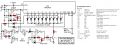
this chaser, not working! any problems visible?

Thread Starter

devoided

Joined Apr 2, 2021
28
I don't have pcb, so I tried making it on a plywood, but bummer, not working! any problems visible? IMG_20211021_110645_335.jpg


IMG_20211021_110653_022.jpg
1634808756764.png

Moderator's note: Schematic rotated so people can read it without too much trouble and shrunk down from 12 Mega Pixels.
 
Last edited by a moderator:

DickCappels

Joined Aug 21, 2008
10,169
I think this is a flasher rather than a chaser - only one LED visible and no circuitry to supply more than one phase of a flash.

Some things to think about:

No bleeder resistors across your high voltage capacitor! Believe me, please, if you use this and then handle the board later you are likely to receive a nasty shock.

Plywood - not fire retardant -be careful and don't leave this running unattended, please!

Is the first diode a Zener, if so, what voltage?

I cannot determine the capacitance, voltage rating and type of C2.

What are the purposes of the +Ve and -Ve connections. This circuit is dangerous, this circuit needs to be isolated from earth and all things that intent to keep living on earth.
 

MisterBill2

Joined Jan 23, 2018
18,461
The circuit drawing is readable as posted, so that is a big improvement. It looks like there is an intended voltage doubler but not quite right. I do not understand the purpose of the triac in series with the LED, either.

I suggest finding some aplication notes for the 555 timer IC I an sure that there are some flashers in that area and it is OK to copy published circuits to learn from.

And using plywood for a circuit base is actually a good idea. It has been done before with great success. Just be careful to not char the wood when soldering, because charred wood will conduct electricity to some extent.
 

DickCappels

Joined Aug 21, 2008
10,169
LEDs to mains and transformerless power supplies are now allowed. Unsafe circuits and practices are not.

the two diodes and capacitors at the input looks like the circuit in a Microchip application note. The first is a Zener diode that clips the peak input voltage to 5.6 VDC and the following diode and capacitor peak detect the waveform to get 5 VDC across the capacitor in the cathode of the peak detector. The input capacitor limits the current into the Zener and the 100 ohm resistor in series is for transient protection -mainly for the switch-on transient.

You are right, the trial is out of place in this DC circuit.
 

Tonyr1084

Joined Sep 24, 2015
7,894
Here's a 20 LED chaser I built a while ago. It's purely 5VDC. The IC's used are the CD4017BD and CD4013BD. The 4017 is a Decade Counter; with each pulse it moves forward. First from 0 to 1, then to 2, through to 9. Then the carry-out pin clocks the 4013, which is a dual D flip flop. It merely toggles back and forth between transistors Q2 & Q3. When transistor Q2 is on D11 through D20 is what's pulsed via the 4017. When 4017 carries out the 4013 switches transistor Q2 off and transistor Q3 on, which chooses D1 through D10. This process is continuously running. The clocking comes from the second half of the flip flop. Q1 pulls the FF low for a brief moment. This is needed to start the chase. Otherwise nothing will happen.

R5 limits the current to the LED's. Remember, only one LED is on at a time, so there's not a whole lot of wattage being dissipated through R5. I used C1 & C2 to get a higher time constant since I was limited in stock at the time. R1 and R2 can be changed to higher values if you want the clock pulse to run slower. Or you could substitute variable resistors in their place to enable sweep rate control. No 555 was used. Since I was only using half of the FF for the light control the other half could be used to create a multi-vibrator. It just needs that kick start from transistor Q1.
1634828008922.png
 
Last edited:

Audioguru again

Joined Oct 21, 2019
6,688
The polarity of the LED is backwards.
I do not know why there is a triac (it will never turn off with the DC through it) and I do not see a proper triac gate circuit to prevent the high voltage from destroying its gate.
 

Tonyr1084

Joined Sep 24, 2015
7,894
I think the 240V(AC) is a wall wart not properly represented. If this is the case, and the WW is just a phone charger, something like 5V output then you don't need to show it on your drawing. Only represent the 5V Plus and Minus, as it appears you have done, but in a confusing way.

There are plenty of LED Flasher circuits on the internet. If all you want is a single flashing LED - that's quite easy. All we need to know is what frequency do you want it to flash at and whether you want it ON for a certain period of time and OFF for the rest of the cycle. In other words; ON 75%, OFF 25% at a rate of 5Hz (five flashes per second) ((or whatever flash rate you want)).
 

Audioguru again

Joined Oct 21, 2019
6,688
There is no 5V wall wart. There is 240VAC feeding a 0.68uF capacitor in series with 100 ohms and feeding a zener diode. Then it has a useless rectifier that feeds the DC pulses to a filter capacitor and to the 555 oscillator.

I agree that it is not a Chaser circuit. Most CD4017 chasers drive each LED with squarewaves jerking sudden on and off. Some of my CD4017 chasers use a capacitor with each LED so that they appear to smoothly fade.
I have battery powered chasers that use a Cmos low current oscillator and a Cmos circuit that blinks each LED for a short time duration to save battery power.
Here is my 3V chaser circuit:
 

Attachments

dl324

Joined Mar 30, 2015
16,909
I don't have pcb, so I tried making it on a plywood
It would be safer for you to wire dead-bug style with no board. You need to make sure you wire correctly because rework could be painful.

Your "schematic" would be easier to read if you used a more typical symbol for the timer (inputs primarily on the left, output on the right) and put component values by the components instead of in a table.
 

Tonyr1084

Joined Sep 24, 2015
7,894
This is why I'm suspecting a wall wart. I can't imagine anyone building a supply and use a barrel connector on a 240VAC line. I could be wrong.
1634833038103.png
 

Tonyr1084

Joined Sep 24, 2015
7,894
If the 240V was actually a DC wall wart then C3 would block all current.
Triac - LED backwards - who's to say there aren't more errors in the drawing. I think none of us have enough confidence in the drawings or the skills of the TS. I'm not saying the TS is not smart, just saying there can be other errors as well. I'm not even sure how this (-Ve & +Ve) comes into play.
1634835322208.png
 

DickCappels

Joined Aug 21, 2008
10,169
At this point I think we can definitely say that the triac should be removed and the LED be reversed so that the anode comes from pin 3 of the NE555 (NOt pin 7 as it appears), so maybe we can added the NE555 being wired incorrectly to the list.

Of course we should suspend judgement until the thread starter describes the circuit they want.
 

ElectricSpidey

Joined Dec 2, 2017
2,774
It looks to me like the LED is connected to pin 3. (but it is backwards)

It also looks to me like the LED is supposed to remain off until the gate signal becomes present, then starts to flash until the gate signal is removed and the 555 goes low.
 

Thread Starter

devoided

Joined Apr 2, 2021
28
my mistake, the triac is backwards, but the led flashes together with the others in the load, so it remains that way
 

zophas

Joined Jul 16, 2021
165
There is no 5V wall wart. There is 240VAC feeding a 0.68uF capacitor in series with 100 ohms and feeding a zener diode. Then it has a useless rectifier that feeds the DC pulses to a filter capacitor and to the 555 oscillator.

I agree that it is not a Chaser circuit. Most CD4017 chasers drive each LED with squarewaves jerking sudden on and off. Some of my CD4017 chasers use a capacitor with each LED so that they appear to smoothly fade.
I have battery powered chasers that use a Cmos low current oscillator and a Cmos circuit that blinks each LED for a short time duration to save battery power.
Here is my 3V chaser circuit:
Nice chaser that, @Audioguru again. I built the 6v version years ago, it's been running in a corner of the kitchen for ages.
 
Top