I thought speakers were rated in watts. I don't think 100mA would wreck my speaker especially when my supply voltage at worst case right now is 8, and I already tried the speakers in the frying transistor circuit. and to this day the speakers by themselves continue to work because I made an older amplifier design that really distorts at the 5-6V range using the same speakers. The speakers are rated for 20W and I'm sure I posted a picture or link to them on this site before. (each one was about $13 each from digikey)
I've heard I'm pretty sure worse than 5% distortion from my amp when the battery level was dropping.
I take it as a factor in my whole design because to me it determines how long a battery can live. It seems what affects the output amplitude the most are the resistors connected to the base of the NPN transistors.
Mike, the distortion we are talking about is not clipping distortion. When your battery voltage drops then you must turn down the volume to avoid clipping distortion.
The distortion of a single transistor is extreme at high levels but without clipping. Your simple amplifier has only one transistor that produces voltage gain. The ratio of base and collector resistors determines the voltage gain, and the biasing.
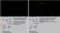
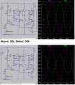
Here is some typical transistor distortion but without clipping:
I've had those roundish waves when my base (negative feedback) resistor driving the 2N2222 was too high and probably the connecting bootstrap capacitor made it rounder to prevent annoying sounds. Wave probably would look triangular at that point with no capacitor but I'm leaving the capacitor in as I get better results with it in.
This will still happen just not as easy . . A bootstrap cap can do a very cool thing and swing outside the power rails ( aka drive a transistor closer to a rail than a current source or a resister network. )
It is inevitable that you will get distortion as your voltage supply drops below what the circuit needs, or you ask for a voltage swinger bigger that the voltage your supply has .. I imagined this was why you switch to a BRIDGE.. know you have 2x the voltage swings even when it drops still 2x voltage swing.
Listening test at volumes you intend will tell you what voltage or the power you need .. if the old amp sound good till the battery got a bit fatigued you could be well within a comfortable listening arena as voltages drop. If your hoping to to get more drive from a bridge over time .. Bad news it sees your speaker as a 4ohm so will burn 50% more power for same playing time at this new higher volumn/voltage.
If I'm not mistaken, would an idle output current of 100mA with 8V supply make the TIP4x transistors stay cool to the touch? I mean my math leads me to 800mW and double that is 1.6W which is under 2W, then again someone mentioned some specs (particularly with wattage handling) were for marketing purposes?
With an 8v supply, two transistors are in series on each side of the bridge. Then 800mA x 4V (half of 8V)= 3.2W. Each transistor heats with 3.2W so four transistors heat with 12.8W.
I don't mind if I need some kind of heatsinks when loud music is playing. and I don't think my design will ever exceed 65W. I think my peak (according to the sim) is about 12W with music playing. It just would be nice if the parts are cool (or at least not oven-hot) when I have no music playing.
[/QUOTE]
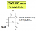
You need an adjustable pair of diodes (adjustable voltage multiplier) made with a transistor and a potentiometer. The transistor can be bolted to the heatsink of the output transistors to automatically detect and adjust the idle current when temperature changes tries to change the idle current.
I thought speakers were rated in watts. I don't think 100mA would wreck my speaker especially when my supply voltage at worst case right now is 8, and I already tried the speakers in the frying transistor circuit. and to this day the speakers by themselves continue to work because I made an older amplifier design that really distorts at the 5-6V range using the same speakers. The speakers are rated for 20W and I'm sure I posted a picture or link to them on this site before. (each one was about $13 each from digikey)
speakers work from AC
The voltage alternates which causes the speaker cone (piston) to alternate back and forth.
DC cause the magnetic speaker to push is cone away from center then any AC sounds might cause its cone to smash into the magnet structure and be destroyed. DC in a speaker also might overheat it.
Amplifier idle current is in the amplifier output transistors, not in the speaker. The DC idle voltages on the output of each bridge amplifier half are supposed to be identical preventing DC in the speaker.
With out component type or circuit change .. R6 is controlling the transistor current. Q1 appears locked in A never turning off. as you increase R6 you will provide less current to the base of q1 and and also to the diodes that are actual drawing and driving the base of q3.
Look at bumping r6 .. or add a variable resister to help pull the tip41 out of idle heating. Was the tip41 that were getting worm when idle ?
With an 8v supply, two transistors are in series on each side of the bridge. Then 800mA x 4V (half of 8V)= 3.2W. Each transistor heats with 3.2W so four transistors heat with 12.8W.
Also, I don't understand the benefit of making R5 56k instead of 39K because when I make it a high value then the output at B looks like its half of output A at best and wouldn't that make the speaker work funny because one end would partly push (because of lower voltage) while the other end completely pulls or vice-versa (because of higher voltage)?
You said 800mA in post #136 but did not say if it is idle current or momentary peak current.
With a 7.2V supply and a 7.2 ohm speaker, if one side of the bridge goes to +6.8V and the other side goes to +1V then the momentary total peak voltage is 5.8V and the momentary peak current is 5.8V/7.2 ohms= 806mA.
r5 is just how much of the signal out from left side of to input right side. Any thing changes this will be effected ..
IF those came from me i was just hacking around .. the 4007 are a bad idea .. You shouldl ponder diodes with a lower turn on not a larger .. And 56k not sure what i was looking at .. So Sorry .
View attachment 278023
Also, I don't understand the benefit of making R5 56k instead of 39K because when I make it a high value then the output at B looks like its half of output A at best and wouldn't that make the speaker work funny because one end would partly push (because of lower voltage) while the other end completely pulls or vice-versa (because of higher voltage)?
I showed in post #118 that my "b" amplifier voltage gain was too high so increasing the 39k to 56k fixed it.
Maybe because your circuit is not at max level before clipping.
Mine goes almost up to the supply voltage and down to +1V which is almost clipping but yours is far from clipping.
Mine has a voltage gain of 5.4 times on each side but yours has only 3.3 times on each side.
Hey, did the 1N4007 diodes reduce the idle current? How much?
With a 7.2V supply and a 7.2 ohm speaker, if one side of the bridge goes to +6.8V and the other side goes to +1V then the momentary total peak voltage is 5.8V and the momentary peak current is 5.8V/7.2 ohms= 806mA.
Ok, so a bigger waveform on one output and a smaller waveform on the other output I guess can reduce peak current consumption but wouldn't that make the overall volume of sound lower?
Ok, so a bigger waveform on one output and a smaller waveform on the other output I guess can reduce peak current consumption but wouldn't that make the overall volume of sound lower?
Yes. On a bridged amplified each side must swings the same amount but inverted. Never mind the peak positive voltages because the bootstrapping allows it to almost be reach the supply voltage. The negative-going swing does not go down to ground, instead it goes only as low as +1V.
But if one side goes up 2V then the other side should go down 2V.
I'm wondering if I got my math right.
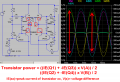
So for the transistor power, I'm doing an NPN and PNP as one unit and I'm taking the peak points of the current values and the peak points of the voltage. (see red arrows). and I'm subtracting the two values at each peak then I multiply to get the total watts. because there's 2 transistors, I divide the answer by 2 to know the wattage going through each transistor. Am I accurate with how I'm calculating worst-case wattage requirements when playing music?
and the circled parts in the schematic were what I clicked on to produce the waveforms.
Amplifier power is measured in continuous RMS voltage and current. When the signal is a sinewave then a simple calculation converts the peak to RMS.
Your input signal is too low, turn it up to clipping then down a little to eliminate the clipping.
Now the output voltage swing is 6.5V to 2V which is 4.5Vp-p. Only 1.41W bridged into 7.2 ohms at fairly low distortion.
Before the max output swing was 7.8V to 1V which is 6.8Vp-p. More bridged power of 3.21W (2.3 times more power).
Amplifier power is measured in continuous RMS voltage and current. When the signal is a sinewave then a simple calculation converts the peak to RMS.
Your input signal is too low, turn it up to clipping then down a little to eliminate the clipping.
Now the output voltage swing is 6.5V to 2V which is 4.5Vp-p. Only 1.41W bridged into 7.2 ...
you lost me at the 1.41W.
I had current values in the 500-600mA at max peak and multiplying that by 4.5 doesn't give me 1.41W. What current value are you use and from where to get 1.41W?

 Facebook
 Google
 GitHub
 Linkedin