The TIP42 in bridged class ab amp is hot.

Ian0

Joined Aug 7, 2020
13,230
replaced 2 diodes with 1 diode and 1 resistor. Resistor value of about 33 ohms gives about 3mA which is nice, but at 5V, the waveform looks like crossover distortion in the middle. Then I increased the resistance at 5V and the crossover distortion is removed, but when I raised the voltage back to 8V, the current is now at least 200mA which is an all-time new high.
If you made a amplifier with a decent amount of open-loop gain, then the feedback would remove most of the crossover distortion, and would nicely set the DC output conditions into the bargain.
For instance my circuit
https://forum.allaboutcircuits.com/...ors.189365/page-2#lg=attachment276954&slide=0
that I gave you on September 24th or @ericgibbs circuit from post #55.
 

Thread Starter

mike_canada

Joined Feb 21, 2020
239
After all this time.....
rise.png


My answer lies in the thermal characteristics.
I don't think my heatsinks were wonderful (they were simple C-shaped heat sinks). I also did not have any thermal compound or equivalent, and when I complained about overheating transistors without proper heatsinks, maybe the real total temperature per transistor was about 114 degrees (57 x 4 watts power divided across 2 power transistors). then add room temperature so that's 135 degrees and the limit is 150 before malfunction.

So therefore, my answer is to pay more attention to the characteristics in the table and watch how many watts I deliver to the speaker or I could upgrade the transistors but they can be pricey.
 

Audioguru again

Joined Oct 21, 2019
6,826
You are not going to play a continuous loud tone, instead you will play music that is loud only momentarily and has loudness dynamics and even pauses in it.
Get the idle current down then the average output heating power with loud music is1/5th to 1/10th a continuously loud tone.
 

BobTPH

Joined Jun 5, 2013
11,619
A few misconceptions in your last post.

1. The 57 degrees is with no heat sink. If you have a heat sink you would add junction to case, case to heatsink, and heatsink to ambient to determine the junction temperature.

2. The power delivered the the speaker has nothing to do with the heating of the transistor. It is the power wasted in the transistor that heats it. A large quiescent current heats the transistor with no power delivered to the speaker.

3. In a linear application, upgrading the transistor does nothing the mitigate the power dissipation. A different package could help a little for the case with no heat sink.
 

Audioguru again

Joined Oct 21, 2019
6,826
The power delivered the the speaker has nothing to do with the heating of the transistor.
No. This amplifier is a linear class-AB push-pull design. It is about 50% efficient so with an output of 10W its heating is also about 10W.

You are talking about a switching class-D design where the output transistors switch on and off and are never linear:
1) When an output transistor switches full-on then the voltage across it is very low then its heating is very low.
2) When an output transistor switches off then its current is very low then its heating is very low.
 

Thread Starter

mike_canada

Joined Feb 21, 2020
239
1. The 57 degrees is with no heat sink.
Yes I meant to say that because for a heat sink to be effective, it has to be good quality and thermally connected but normally when I attach heatsinks, I use screws. I don't own thermal compound or the like. It's expensive.

3. In a linear application, upgrading the transistor does nothing the mitigate the power dissipation. A different package could help a little for the case with no heat sink.
It may benefit me greatly because looking at upgraded transistor prices vs the price of thermal compound and heatsinks makes me think that I'm better upgrading to a TO-3 style transistor that basically has a heatsink already embedded onto it, so then I could avoid the need of thermal compound.

I don't have the resources to apply the heatsink 100% to a TO-220 package (no thermal compound)
 

Audioguru again

Joined Oct 21, 2019
6,826
Thermal resistances, junction to case:
TO-220 for a TIP41= 1.67 degrees C/W.
TO-3 for a 2N3055= 1.52 degrees C/W. Not much difference.

The plastic (epoxy?) TO-220 max allowed chip temperature= 150 degrees C but the all-metal TO-3 has a max of 200 degrees C.

Your tiny C-shaped heatsinks don't cool as much as larger aluminum finned heatsinks.
 

Martin_R

Joined Aug 28, 2019
137
It's been said many,many times that your standing current is too high, particularly so for a battery powered amp of relatively low output power. Heatsinking requirements SHOULD be small for a low power battery powered design, and for minimum added complexity you could build an amplifier that is stable over voltage variations, has low standing current and has plenty of gain so negative feedback could keep distortion low.
Or you could just buy a cheap class D amp .
 

Ian0

Joined Aug 7, 2020
13,230
An Amplifier powered from 7.2V can deliver 0.9W into an 8Ω load and if well designed will do so with an efficiency of 70%. That should result in a dissipation of 0.3W per output transistor. There is no way it should need a heatsink.
No amount of fiddling with the TS’s design is going to make it into anything other than a rubbish amplifier. The gain is too low, so that there isn’t enough feedback to remove the distortion, so the only way for it to sound reasonable is to bias it almost into Class-A.
 

BobTPH

Joined Jun 5, 2013
11,619
An Amplifier powered from 7.2V can deliver 0.9W into an 8Ω load and if well designed will do so with an efficiency of 70%. That should result in a dissipation of 0.3W per output transistor. There is no way it should need a heatsink.
No amount of fiddling with the TS’s design is going to make it into anything other than a rubbish amplifier. The gain is too low, so that there isn’t enough feedback to remove the distortion, so the only way for it to sound reasonable is to bias it almost into Class-A.
Can you show the calculation on that? I think that is a theoretical max if the output swings rail-to-rail, which is pretty far from reality for BJTs in the standard common emitter push-pull stage. Losing 1V on each side would be closer to reality and would be less than 50% efficiency I think.
 

Ian0

Joined Aug 7, 2020
13,230
Can you show the calculation on that? I think that is a theoretical max if the output swings rail-to-rail, which is pretty far from reality for BJTs in the standard common emitter push-pull stage. Losing 1V on each side would be closer to reality and would be less than 50% efficiency I think.
It’s an estimate (perhaps based on amplifiers with higher voltage supplies where the peak output is a higher percentage of the rail voltage). The theoretical maximum is π/4. Even at 50% the dissipation would be 0.9W which is well within the capabilities of two freestanding TO220 packages.
 

BobTPH

Joined Jun 5, 2013
11,619
It’s an estimate (perhaps based on amplifiers with higher voltage supplies where the peak output is a higher percentage of the rail voltage). The theoretical maximum is π/4. Even at 50% the dissipation would be 0.9W which is well within the capabilities of two freestanding TO220 packages.
Also, his amp is bridged, so 4 times the power out at the same voltage. With 1V loss from each rail, the swing is 5.2V for output of 1.7 W still doable with a TO220 as long as you don’t touch the transistors.

Unfortunately, he refuses to listen to us about quiescent current.
 

Ian0

Joined Aug 7, 2020
13,230
Also, his amp is bridged, so 4 times the power out at the same voltage. With 1V loss from each rail, the swing is 5.2V for output of 1.7 W still doable with a TO220 as long as you don’t touch the transistors.
It would be rather less for audio, than for a sinewave, so might not burn your fingers after all.
Unfortunately, he refuses to listen to us about quiescent current.
Because the distortion goes through the roof when the bias is reduced, because he hasn‘t got enough gain and feedback.
And what has he done after 218 posts? changed the resistors on the VAS and changed them back again?
 

MrChips

Joined Oct 2, 2009
35,031
TS has continued to ignore me even though many times I have offered to help. So I am going to stick my neck out.

Here is what we know. TS began with an obsession of wanting to calculate amplifier output power. TS wanted to build a high power portable audio amplifier with minimum distortion running on a 9V battery. TS is on a limited budget.

Here is what TS is doing wrong (for starters).

1) TS has not stated the application of the audio amplifier. Is it for break-dancing in the park, busking on the streets, playing loud sounds to scare away critters?

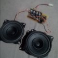
2) TS has experimented with various loudspeakers starting with totally inadequate 2" PC speakers. These are his current speakers.

mike_canada loudspeakers.jpg

TS has been told repeatedly that the loudspeaker is just part of the solution. It needs to be in an enclosure.

TS has been told that there is a front acoustic wave and a back acoustic wave. The back wave is 180° out-of-phase with the front wave. Hence they cancel producing reduced volume particularly at lower frequencies.

TS has been told to build a speaker enclosure. TS claims there is no money to build a speaker cabinet!

And the saga continues...
 
Top