
 Facebook
 Google
 GitHub
 Linkedin

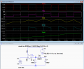
Here's an LTspice simulation of a simple inverting boost converter using one switch and a diode.
When the switch is on, the supply voltage is applied to the inductor and its current increases, adding energy to the inductor magnetic field.
When the switch is off the inductor current decreases as it charges the output capacitor through the diode, transferring the inductive energy into capacitive energy.
The inductor voltage [V(1)] goes between -5 when charging, and the plus output voltage (plus the forward diode drop) when the switch is off, showing the voltage reversal on the inductor, while the inductor current direction does not change (only the current slope changes).
When the switch is on, the supply voltage is applied to the inductor and its current increases, adding energy to the inductor magnetic field.
When the switch is off the inductor current decreases as it charges the output capacitor through the diode, transferring the inductive energy into capacitive energy.
The inductor voltage [V(1)] goes between -5 when charging, and the plus output voltage (plus the forward diode drop) when the switch is off, showing the voltage reversal on the inductor, while the inductor current direction does not change (only the current slope changes).
Attachments
-
1.2 KB Views: 1
Last edited:

 while the capacitor looks like a rectangular mass





