The collapse of a magnetic field

Thread Starter

thew

Joined Feb 24, 2017
8
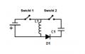
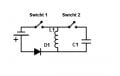
Hi Guys, whats up?, I m trying to create a circuit very difficult about the possibilities of charge a capacitor using the collapse of a magnetic field of a inductor where the inductor is previously charged obviously from a external source of power such as a battery as is showed in the circuit I attached, the real difficulty here is the switch 1 must be turned on when the switch 2 is off, and the switch 2 must be turned on instantly when the switch 1 is off, the Simultaneity must be perfect, it must be instantly at the same time in order to take advantage entirely the collapse of the magnetic field to charge the capacitor, I drew in the circuit switches to understand what I want, but I think the best way will be to use other electronic component, but I don't know what electronics components are able to do something like that, I hope somebody can help me
 

Attachments

AlbertHall

Joined Jun 4, 2014
12,345
In the second diagram, leave S2 closed and reverse the diode.
The collapsing magnetic field will generate a voltage across the inductor in the opposite direction to that which produced the current in it.
 

Thread Starter

thew

Joined Feb 24, 2017
8
But still, must be something to make it a automatic switching, and I don't know how to do that
 

AlbertHall

Joined Jun 4, 2014
12,345
But still, must be something to make it a automatic switching, and I don't know how to do that
The diode does the automatic switching because the voltage across it reverses when S1 is opened. This is how switched mode power supplies work. Have a look at the buck-boost circuit here where the function of your S1 is performed by a transistor switch.
 

Thread Starter

thew

Joined Feb 24, 2017
8
Hi,

You mean automatically switch the first switch too?

This is just a boost converter.
I was watching the circuit of a boost convertor over internet but is not exactly the same, because, in the boost convertor circuits the capacitor is charged directly from the power source, and I want the capacitor CHARGED ONLY from the inductor. Also I was looking the possibility to use transistors but I m not sure if it could be the solution.
 

AlbertHall

Joined Jun 4, 2014
12,345
The first switch is automated in a power supply. In the link I gave you can see the various possible arrangements of switch, inductor, diode and output capacitor and the names given to each arrangement. The arrangement which your circuit mimics is the buck-boost version which produces an output voltage of opposite polarity to the input voltage. In this arrangement the output current comes only from the inductor, never directly from the input power.
 

Thread Starter

thew

Joined Feb 24, 2017
8
In the second diagram, leave S2 closed and reverse the diode.
The collapsing magnetic field will generate a voltage across the inductor in the opposite direction to that which produced the current in it.
I can not do that, if I do that, then the diode will be close the circuit in order to charge the capacitor from the collapse of the magnetic field of the coil, the diode is correctly oriented in the second attached it is allowing to receive the charge to the capacitor and cancelling any discharge from the capacitor to the coil
 

AlbertHall

Joined Jun 4, 2014
12,345
If you do that then when S1 is closed the input voltage is connected across the coil and via the diode to the capacitor. When the switch is opened and the magnetic field is collapsing, the voltage across the inductor will reverse and the diode will be reverse biased and there will be nowhere for the inductor current to go. This will generate a large voltage and arc across the switch contacts as they open.
 

Thread Starter

thew

Joined Feb 24, 2017
8
The first switch is automated in a power supply. In the link I gave you can see the various possible arrangements of switch, inductor, diode and output capacitor and the names given to each arrangement. The arrangement which your circuit mimics is the buck-boost version which produces an output voltage of opposite polarity to the input voltage. In this arrangement the output current comes only from the inductor, never directly from the input power.
Seems you have reason, but I don't understand it, when you put current to a inductor and after you cut off the current, the inductor must generating then a current but it supposedly has to be a opposite current, in the
Buck-Boost circuit it is saying that the inductor generates a current in the same direction when it was charged
 

AlbertHall

Joined Jun 4, 2014
12,345
Seems you have reason, but I don't understand it, when you put current to a inductor and after you cut off the current, the inductor must generating then a current but it supposedly has to be a opposite current, in the
Buck-Boost circuit it is saying that the inductor generates a current in the same direction when it was charged
The current in an inductor when the field is collapsing is in the same direction as when the field was building. The induced voltage across the inductor is in the opposite direction as when the field was building. It is known as a back emf for that reason.
 

Thread Starter

thew

Joined Feb 24, 2017
8
The current in an inductor when the field is collapsing is in the same direction as when the field was building. The induced voltage across the inductor is in the opposite direction as when the field was building. It is known as a back emf for that reason.
Then it is different from a capacitor, right? when you charge a capacitor and after you discharge it is as a spring, its reverses the current, but a inductor is not as a spring, when a inductor is being charged the magnetic field is trying to oppose the current and for that reason when the magnetic field collapses goes in the same direction?
 

AlbertHall

Joined Jun 4, 2014
12,345
Yes, capacitors and inductors are kind of opposites. A capacitor opposes change of voltage where an inductor opposes changes of current.
 

MrAl

Joined Jun 17, 2014
11,396
Hello again,

The inductor is sometimes called the "dual" of the capacitor.
This is because what happens for the voltage across a capacitor happens for the current in an inductor, and what happens for the current in a capacitor happens for the voltage across an inductor.

In a mechanical analogy (force-current), the capacitor is often taken to be the mass while the inductor a spring.
 

nsaspook

Joined Aug 27, 2009
13,086
Hello again,

The inductor is sometimes called the "dual" of the capacitor.
This is because what happens for the voltage across a capacitor happens for the current in an inductor, and what happens for the current in a capacitor happens for the voltage across an inductor.

In a mechanical analogy (force-current), the capacitor is often taken to be the mass while the inductor a spring.
Correct, and together they form a system of simple harmonic motion that can store and release energy over time.


crutschow

Joined Mar 14, 2008
34,285
In a mechanical analogy (force-current), the capacitor is often taken to be the mass while the inductor a spring.
I thought it was the other way around.
The spring is like a capacitor, the movement (integrated current) is proportional to the force (voltage).
The mass is like an inductor, the acceleration (rate of current increase) is proportional to the force (voltage).
 

nsaspook

Joined Aug 27, 2009
13,086
I thought it was the other way around.
The spring is like a capacitor, the movement (integrated current) is proportional to the force (voltage).
The mass is like an inductor, the acceleration (rate of current increase) is proportional to the force (voltage).
Take your pick of analogies:
(Force-Current) C Mass energy
or
(Force Voltage) C Spring energy
 
Top