Testing a motor's capacitor's health

Pyrex

Joined Feb 16, 2022
513
There is a simple and reliable way to check the capacitor, but you need to have an AC ammeter. The capacitors need to be connected to the electrical outlet and the current must be measured. The current of a 1 microfarad capacitor at 230V 50Hz is about 70 mA. Therefore, a 20 microfarad capacitor should consume about 1.4 A of current.
If the voltage or frequency is different, the current needs to be recalculated.

Xc=1/ ( 2*3.14*f*C) , where f is frequency , C is capacity

I= U/Xc ,where U is voltage

After the test, disconnect the capacitor from the power source and discharge it. A charged capacitor can hold its charge for several days and can cause an electric shock !
 

Thread Starter

Tp86

Joined Sep 13, 2023
213
There is a simple and reliable way to check the capacitor, but you need to have an AC ammeter. The capacitors need to be connected to the electrical outlet and the current must be measured. The current of a 1 microfarad capacitor at 230V 50Hz is about 70 mA. Therefore, a 20 microfarad capacitor should consume about 1.4 A of current.
If the voltage or frequency is different, the current needs to be recalculated.

Xc=1/ ( 2*3.14*f*C) , where f is frequency , C is capacity

I= U/Xc ,where U is voltage

After the test, disconnect the capacitor from the power source and discharge it. A charged capacitor can hold its charge for several days and can cause an electric shock !
Thats a good way of testing at a real operating voltage thanks! I have a automotive clamp ammeter but it only works within the range of 600A – 1000A.
Can you recommend a good ac ammeter for testing about 1.4A? If not thats ok I'll do some research
 

Pyrex

Joined Feb 16, 2022
513
Thats a good way of testing at a real operating voltage thanks! I have a automotive clamp ammeter but it only works within the range of 600A – 1000A.
Can you recommend a good ac ammeter for testing about 1.4A? If not thats ok I'll do some research
The ammeter you have can be easily adapted to measure small currents. Wrap the wire around the ammeter's current clamp,let's say 10 turns. Then your ammeter will show a current 10 times smaller. If the display shows, let's say, 100 amperes, but the actual current is 10 amperes.
 

MrAl

Joined Jun 17, 2014
13,726
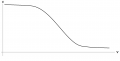
Thanks mate. I had a go at simulating this and it seems like its dropping off way to fast. What do you think? Have I made an error?
Well I did not want to get too exact with this, that was just a quick example of how the function might work.
In reality, it would stay more horizontal for a bit, then start falling faster and faster until it started to level off again, and at some low level it would taper off much more slowly.
This would be similar to how an inductor inductance decreases with increasing current. If we start with a BH curve, we could come up with that formula and it should look similar to the capacitor plot. See attachment.
The difference is, in domain theory the domains flip and in dipole theory the dipoles flip. "Sort of" the same thing, almost.

I'd have to hunt around for the better formula but I do think I have it somewhere.
 

Attachments

MisterBill2

Joined Jan 23, 2018
27,741
Consider also that there is a whole class of motors, identified as "Permanent Split Capacitor" types, that are very conveniently reversible, and also use a capacitor and have two identical windings.

@ Pyrex: That is a good way to check capacitors, but probably the test should be short, to avoid overheating and explosion damage. Even in a good capacitor, there will be a fair amount of power dissipated as heat.
 

Thread Starter

Tp86

Joined Sep 13, 2023
213
The ammeter you have can be easily adapted to measure small currents. Wrap the wire around the ammeter's current clamp,let's say 10 turns. Then your ammeter will show a current 10 times smaller. If the display shows, let's say, 100 amperes, but the actual current is 10 amperes.
Genius trick. I did not know that one. So the basic pricipal is that each loop around the clamp will increase the multiplication factor of the magnetic field the clamp see's by 1. So 10 loops means the clamp see's 10 times the current than what is actually going around the circuit.

The only drawback I see is that we in process are creating a small inductor. However its reactance effects should be almost neglegible. Thanks for the trick Pyrex. Genius level improvisational skills
 

MrAl

Joined Jun 17, 2014
13,726
Thats a good way of testing at a real operating voltage thanks! I have a automotive clamp ammeter but it only works within the range of 600A – 1000A.
Can you recommend a good ac ammeter for testing about 1.4A? If not thats ok I'll do some research
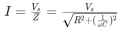
You don't need an ammeter really. You can use a frequency generator and your scope. Use a resistor in series with the cap and measure the cap voltage, then relate it to the formula:
vC=Vs/sqrt(w^2*C^2*R^2+1)
w=2*pi*f
Vs is applied AC voltage

If you test at line frequency you can use an ammeter.
 

MrAl

Joined Jun 17, 2014
13,726
Genius trick. I did not know that one. So the basic pricipal is that each loop around the clamp will increase the multiplication factor of the magnetic field the clamp see's by 1. So 10 loops means the clamp see's 10 times the current than what is actually going around the circuit.

The only drawback I see is that we in process are creating a small inductor. However its reactance effects should be almost neglegible. Thanks for the trick Pyrex. Genius level improvisational skills
Yeah it's amazing, and you can even buy one on Amazon :)
 

Thread Starter

Tp86

Joined Sep 13, 2023
213
Well I did not want to get too exact with this, that was just a quick example of how the function might work.
In reality, it would stay more horizontal for a bit, then start falling faster and faster until it started to level off again, and at some low level it would taper off much more slowly.
This would be similar to how an inductor inductance decreases with increasing current. If we start with a BH curve, we could come up with that formula and it should look similar to the capacitor plot. See attachment.
The difference is, in domain theory the domains flip and in dipole theory the dipoles flip. "Sort of" the same thing, almost.

I'd have to hunt around for the better formula but I do think I have it somewhere.
Intestering. This seems like quite a big topic to research on its own. I'll take your word for it, its like a BH curve. Down the track I'll look into it more. Thanks mate.

You don't need an ammeter really. You can use a frequency generator and your scope. Use a resistor in series with the cap and measure the cap voltage, then relate it to the formula:
vC=Vs/sqrt(w^2*C^2*R^2+1)
w=2*pi*f
Vs is applied AC voltage
I think I see what your saying here. Adding a series resister to the circuit would then allow you to measure the current.
1755519727477.png
The only drawback I see is that adding a resister itself will add unwanted impedance to the current which will effect measurement. (The goal was to measure how much current flows through the capacitor to determine if its healthy) But if we used a low value shunt resister, this impedance would bearly effect the measurment. Was this you had in mind?
 

Thread Starter

Tp86

Joined Sep 13, 2023
213
Consider also that there is a whole class of motors, identified as "Permanent Split Capacitor" types, that are very conveniently reversible, and also use a capacitor and have two identical windings.
Yes, Im almost certain its a PSC motor as it aligns with eveyrthing I've observed

@ Pyrex: That is a good way to check capacitors, but probably the test should be short, to avoid overheating and explosion damage. Even in a good capacitor, there will be a fair amount of power dissipated as heat.
Good point. They are designed to be operated on a winding which experiences a back emf from rotor so its not a senario they were nessisarrily designed for. The winding around clamp for field multiplication is a fantastic trick anyway and will be excited to try that
 

MaxHeadRoom

Joined Jul 18, 2013
30,713
In Australia we dont have split-phase power like you have in North America for the vast majority of situations. We only have access to 3-phase (industrial, commercial, agricultural etc) and single phase for households.
To me it seems like the pump I have has no centrifugal switch at all and the capacitor severs as a start and run capacitor all in one with both operations producing a fairly low field strength to produce the torque in comparison to the main winding. This would also explain why the caps fail after some years
I was NOT referring to the type of power supply, 1ph motors are identical to both N.A. & the rest of the world , as I said before, up to around 1hp 1ph AC motors typically just have the combined start/run capacitor for phase shift.
The whole point of the capacitor(s) is to provide a 90° phase shift in the power applied to the start winding relative to the main power supply.
BTW, the type that has the dual capacitor where the larger value electrolytic is switched out still requires that the secondary winding be supplied with a phase-shifted supply. (run capacitor).
 
Last edited:

MaxHeadRoom

Joined Jul 18, 2013
30,713
Yes, Im almost certain its a PSC motor as it aligns with eveyrthing I've observed
A PSC motor often has both run & start windings of equal resistance value, i.e., both windings are identical. So it can easily be reversed by way of a simple SPDT switch with centre OFF.
 
Last edited:

Pyrex

Joined Feb 16, 2022
513
Consider also that there is a whole class of motors, identified as "Permanent Split Capacitor" types, that are very conveniently reversible, and also use a capacitor and have two identical windings.

@ Pyrex: That is a good way to check capacitors, but probably the test should be short, to avoid overheating and explosion damage. Even in a good capacitor, there will be a fair amount of power dissipated as heat.
The capacitor from the photograph can be connected to a voltage of 420V 24 hours a day
 

Pyrex

Joined Feb 16, 2022
513
Capacitors like the one in the photo have a tendency to lose capacitance when they are connected to a voltage source for a long time. And it seems that the longer they are connected to a voltage source, the more capacitance they lose.

I sometimes have to repair devices that have RFI filters installed- microwaves, SMPS , etc .Most devices work without an RFI filter, so a failure of the RFI filter is not so obvious.But I checked the RFI filter capacitors several times, and found that they had completely or partially lost their capacitance.
And it turns out that about 9 out of 10 RFI filters are bad if the device has been in use for at least 5 years.

We had to dismantle several dozen old fluorescent lights, each of which had a capacitor to suppress RFI, 0.047-0.1 uF, 250-300VAC.
Out of curiosity, we checked them out. Almost all capacitors had a much smaller capacitance than stated on them, or no capacitance at all. If you disassemble such a defective capacitor, you will find that the thin foil looks like torn paper. The integrity of the thin metal is broken, and the broken part of the foil no longer forms a capacitance.
We also dismantled several very old lamps that used paper in oil capacitors, rated to 400 V. These used a fairly thick strip of metal. These ancient capacitors were found exploded, almost all of them.
It seems that high voltage spikes occur in the power grid from time to time, and they partially or completely damage the RFI capacitors
 

Thread Starter

Tp86

Joined Sep 13, 2023
213
A PSC motor often has both run & start windings of equal resistance value, i.e., both windings are identical. So it can easily be reversed by way of a simple SPDT switch with centre OFF.
I doubt it would be a SPDT switch design as a water pump is designed to rotate in only 1 direction. Interesting to know though
 

Thread Starter

Tp86

Joined Sep 13, 2023
213
Capacitors like the one in the photo have a tendency to lose capacitance when they are connected to a voltage source for a long time. And it seems that the longer they are connected to a voltage source, the more capacitance they lose.

I sometimes have to repair devices that have RFI filters installed- microwaves, SMPS , etc .Most devices work without an RFI filter, so a failure of the RFI filter is not so obvious.But I checked the RFI filter capacitors several times, and found that they had completely or partially lost their capacitance.
And it turns out that about 9 out of 10 RFI filters are bad if the device has been in use for at least 5 years.

We had to dismantle several dozen old fluorescent lights, each of which had a capacitor to suppress RFI, 0.047-0.1 uF, 250-300VAC.
Out of curiosity, we checked them out. Almost all capacitors had a much smaller capacitance than stated on them, or no capacitance at all. If you disassemble such a defective capacitor, you will find that the thin foil looks like torn paper. The integrity of the thin metal is broken, and the broken part of the foil no longer forms a capacitance.
We also dismantled several very old lamps that used paper in oil capacitors, rated to 400 V. These used a fairly thick strip of metal. These ancient capacitors were found exploded, almost all of them.
It seems that high voltage spikes occur in the power grid from time to time, and they partially or completely damage the RFI capacitors
Interesting read that fits very well with the title of this thread. There is no doubt the capacitors in our equipment room will be subjected to the odd spike from the grid as there is no surge protection in place. But regardless even the manufacturer says these type of caps are only last some many thousand hours at the high potential. One day when Im bored I'll also open up one of our faulty ones as you did to inspect there metal film for fracturing
 

MrAl

Joined Jun 17, 2014
13,726
Intestering. This seems like quite a big topic to research on its own. I'll take your word for it, its like a BH curve. Down the track I'll look into it more. Thanks mate.


I think I see what your saying here. Adding a series resister to the circuit would then allow you to measure the current.
View attachment 354398
The only drawback I see is that adding a resister itself will add unwanted impedance to the current which will effect measurement. (The goal was to measure how much current flows through the capacitor to determine if its healthy) But if we used a low value shunt resister, this impedance would bearly effect the measurment. Was this you had in mind?
Hi,

Well no, I didn't say that, but you can also do that because i=V/R as you know.

What I was suggesting was that you use R and C in series and power that with a frequency generator, then measure the voltage across the capacitor. The formula then is:
vC=Vs/sqrt(w^2*C^2*R^2+1)

and solving for C we get:
C=sqrt(Vs^2-vC^2)/(w*R*vC)

so that's another test for capacitance.
When there is a problem with a capacitor usually the capacitance goes down to a very abnormal value. That's because it takes almost perfection in the physical structure to get the right value of capacitance.

And yes the current is:
iC=(Vs*w*C)/sqrt(w^2*C^2*R^2+1)
 

Thread Starter

Tp86

Joined Sep 13, 2023
213
Hi mate. I see what you're doing here. It seems like a good way to test capacitance at higher voltages than what my multiple meter and TC-1 tester can do. So to get the value of Vc in your equations, I'd have to measure the voltage drop across the cap with an AC voltmeter/multimeter and the rest of the variables we know.

I like it. Thanks man.

Side note: I came up with a failed theory that maybe we could omit the resister all together and just guess an ESR value of the internal psu unit internal resistance and wire resistance but then realised the voltage drop across a tiny resistance would be too difficult to detect and lead to a very inaccurate measurement.

Well done
 

MrAl

Joined Jun 17, 2014
13,726
Hi mate. I see what you're doing here. It seems like a good way to test capacitance at higher voltages than what my multiple meter and TC-1 tester can do. So to get the value of Vc in your equations, I'd have to measure the voltage drop across the cap with an AC voltmeter/multimeter and the rest of the variables we know.

I like it. Thanks man.

Side note: I came up with a failed theory that maybe we could omit the resister all together and just guess an ESR value of the internal psu unit internal resistance and wire resistance but then realized the voltage drop across a tiny resistance would be too difficult to detect and lead to a very inaccurate measurement.

Well done
That sounds good yes.

Also, you have to be sure you use the same measurements for both the source voltage and cap voltage. If you use RMS for both, or Vpeak for both, or even Vpeaktopeak if you rather, those are all good. Just use the same units for both voltages.

I've done this many times but I like to use the scope to measure both the source voltage and cap voltage, and you can display both at the same time with a two channel scope.
 

Thread Starter

Tp86

Joined Sep 13, 2023
213
That sounds good yes.

Also, you have to be sure you use the same measurements for both the source voltage and cap voltage. If you use RMS for both, or Vpeak for both, or even Vpeaktopeak if you rather, those are all good. Just use the same units for both voltages.

I've done this many times but I like to use the scope to measure both the source voltage and cap voltage, and you can display both at the same time with a two channel scope.
I like it.

At work today I opened waterpump wiring terminal boxes as I thought, why not test the amperage through each winding. I found the following:

Water pump 1

2.7A through the 20uF Capacitor
3.1A through Live wire

Water pump 2

1.86A through 20uF Capacitor
3.67A through Live wire

Water Pump 3

2.48A through 20uF Capacitor
3.44A through Live Wire


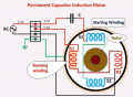
Assuming I've clamped my meter in the correct position which Im almost certain I have, and assuming the motor is basically the same wiring as this diagram than the current though the "Running Winding" would be about 0.4V. Calculated simply by subtracting the current through the cap from the main live wire current. This running winding I thought would actually be drawing more current but perhaps it is not due to having a much larger inductance value.
1755829158953.png


Further info:
- The water pump is rated to run at 4.6A maximum
- The MCB connected is a 10A
 
Last edited:
Top