Testing a motor's capacitor's health

Thread Starter

Tp86

Joined Sep 13, 2023
210
Hi guys.
I have a quick question here. At work we use Lowara water pumps which have a built in single phase (240Vac RMS) motor.

Single phase AC motors of course need a capacitor to help the rotor spin perpendicular with the main coil.

My question today is how can iIreliably test if the capacitor is faulty? The the capacitor specs are as follows
1755229748103.png


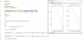
What I have tried is connected a TC1 Muti component tester and running a test. The test results are shown in the picture
3.384uF (much below specification of capacitor label)
0.5ohm ESR (from some research this should be more like 0.1ohm but Im not certain)
IMG20250815132813.jpg


It made me wonder, would the tested capacitance value be soo low because the hand held test device can only test with a very low voltage. If a higher voltage was used (such as 240VRMS which is 340V peak voltage) than it seems like at the plates there would be alot more inward pressure and perhaps that could allow more charge to accumulate on the plates. What do you think? Does anyone have any experience about such things?
 

dendad

Joined Feb 20, 2016
4,636
If the measured capacitance is a lot lower than labeled, toss it out and get a new one.
The tester should read the capacitance ok, the voltage will not change that. There may be leakage at higher voltage but generally, when a capacitor looses its value, that is a good indication of it on the way out.
Just make sure the capacitor is discharged before connecting to the tester unless you want too fry your instrument.
 

Thread Starter

Tp86

Joined Sep 13, 2023
210
Thanks for confiming! I tested 2 capacitors and both read 4uF. Then I had an opertunity to test one in the working motor and it read 20uF 0.5ohm ESR. So 100% the ones reading low are faulty. I'll order a new set. Thanks mate

If a higher voltage was used (such as 240VRMS which is 340V peak voltage) than it seems like at the plates there would be alot more inward pressure and perhaps that could allow more charge to accumulate on the plates. What do you think? Does anyone have any experience about such things?
I just recollected my teachings and remember C = Q / V
In other words it doesnt matter what the voltage value of V is the capacitance will be constant. If you increase the voltage, it does indead do what i say, it adds an increased electric field so more the colombs move to the plate so there will be more charge on each plate. So C is just a ratio value for Q / V depending on how the cap is constructed etc. A good exercise to relearn. Sometimes I forget things. I'm only human. I should update my profile picture so I dont look otherwise
 
Last edited:

MrAl

Joined Jun 17, 2014
13,680
Thanks for confiming! I tested 2 capacitors and both read 4uF. Then I had an opertunity to test one in the working motor and it read 20uF 0.5ohm ESR. So 100% the ones reading low are faulty. I'll order a new set. Thanks mate


I just recollected my teachings and remember C = Q / V
In other words it doesnt matter what the voltage value of V is the capacitance will be constant. If you increase the voltage, it does indead do what i say, it adds an increased electric field so more the colombs move to the plate so there will be more charge on each plate. So C is just a ratio value for Q / V depending on how the cap is constructed etc. A good exercise to relearn. Sometimes I forget things. I'm only human. I should update my profile picture so I dont look otherwise
Hi,

We usually consider the capacitance to stay constant, but that's not really how they work. They do in fact have a voltage dependency. They tend to have a capacitance decrease with increasing voltage. This change would vary with the type of capacitor. For some caps it could be as much as 50 percent, but I don't think there are any of the kind we run into that would decrease by more than that (like 100 percent). Also, AC rated capacitors probably only change a little. You may be able to find this information out on the data sheet. That's the best place to look.

This kind of scenario does not include a gross failure of course. In that case the capacitance can change a lot. A 1000uf cap might start to look like a 10uf cap. It of course means it has to be replaced. I've seen this in electrolytic caps in power supplies.

Sometimes it is hard to test a component or try to figure out a good test for one, so we use the old standby: replace with a new one and see what happens. The only catch here is if we have very bad luck and we get a cap that is already bad when we buy a new one.
 

MaxHeadRoom

Joined Jul 18, 2013
30,593
You normally have one or two motor capacitors, the dry electrolyte start caps, which are in circuit for a couple of seconds, and the oil-filled paper, they can change value over time. The other is the start-run capacitor, which is in circuit all the time. These are usually very rugged types, unless you happen to have a Chinese made ver, which typically can be very unreliable.:confused:
I have very rarely had a motor run cap change value where it is of Western origin.
 

crutschow

Joined Mar 14, 2008
38,400
it seems like at the plates there would be alot more inward pressure and perhaps that could allow more charge to accumulate on the plates.
Since a positive plate is configured with a negative plate on both sides (and vice-versa) in a standard capacitor, then the pressure on the plates varies little with voltage.
 

schmitt trigger

Joined Jul 12, 2010
2,056
A very simple test for motor-capacitors is to wire them in series with a 60W incandescent lamp.
The lamp should light up with slightly diminished brightness. A too-dim light indicates an issue.
Of course, this is only a qualitative test, but it does have the advantage of operating the capacitor under load.
 

Thread Starter

Tp86

Joined Sep 13, 2023
210
Hi,

We usually consider the capacitance to stay constant, but that's not really how they work. They do in fact have a voltage dependency. They tend to have a capacitance decrease with increasing voltage. This change would vary with the type of capacitor. For some caps it could be as much as 50 percent, but I don't think there are any of the kind we run into that would decrease by more than that (like 100 percent). Also, AC rated capacitors probably only change a little. You may be able to find this information out on the data sheet. That's the best place to look.

This kind of scenario does not include a gross failure of course. In that case the capacitance can change a lot. A 1000uf cap might start to look like a 10uf cap. It of course means it has to be replaced. I've seen this in electrolytic caps in power supplies.

Sometimes it is hard to test a component or try to figure out a good test for one, so we use the old standby: replace with a new one and see what happens. The only catch here is if we have very bad luck and we get a cap that is already bad when we buy a new one.
Interesting. I did not know that. The way phyics tests could usually describe it is a linear relationship line below

1755302167566.png
Reference: https://revisionscience.com/a2-level-level-revision/physics-level-revision/fields/capacitors
 

Thread Starter

Tp86

Joined Sep 13, 2023
210
You normally have one or two motor capacitors, the dry electrolyte start caps, which are in circuit for a couple of seconds, and the oil-filled paper, they can change value over time. The other is the start-run capacitor, which is in circuit all the time. These are usually very rugged types, unless you happen to have a Chinese made ver, which typically can be very unreliable.:confused:
I have very rarely had a motor run cap change value where it is of Western origin.
Can you name some brands that have been reliable for you in the past. The only one that came up on google search for me that was non- Chinese was Ducati from Italy. From some more research it looks like Bulgaria make also, 'Kemet'. It needs to be about 450V 20uF with leads (not plug in type) I'd appreciate if you know of a rock solid reliable one to save my brother and one some stress in the future
 

Thread Starter

Tp86

Joined Sep 13, 2023
210
A very simple test for motor-capacitors is to wire them in series with a 60W incandescent lamp.
The lamp should light up with slightly diminished brightness. A too-dim light indicates an issue.
Of course, this is only a qualitative test, but it does have the advantage of operating the capacitor under load.
The ultimate symptom for us is that the motor will trip the breaker if the capacitor is bad. I've done a megger test on the windings to earth and they are all ok so its a current overload issue. It makes me wonder why example this overload occurs. I believe it is because when it tries to start the field generated from the winding with the capacitor is too weak so too much current is moving through the main winding and no back emf to limit it.

Based on this, using the basic mm or tester Farad test should allow me to verify the farad ratio i can store on the cap and thus how much energy it can hold so this starting difficutly never occurs!
 

MaxHeadRoom

Joined Jul 18, 2013
30,593
For the run or start/run caps, I used the oil-filled paper CDE (Cornell Dubilier), they go up to ~20uf.
For the dry electrolyte start types, ensure they are bipolar. motor start and are made in NA, preferably
Kemet, Dayton etc, avoid the Chinese manuf, types.
 

MisterBill2

Joined Jan 23, 2018
27,311
If the complaint is that the motor does not start, and clipping a smaller capacitor across the current cap allows it to start, then certainly the present capacitor has failed. In one case the added cap was simply two 0.47mfd/400 volt paper caps in parallel. That showed that the cap in question was no longer "in spec." So it was replaced, problem solved.
 

MrAl

Joined Jun 17, 2014
13,680
Since a positive plate is configured with a negative plate on both sides (and vice-versa) in a standard capacitor, then the pressure on the plates varies little with voltage.
Hi,

This is interesting.

I think the pressure varies with the square of the voltage, but that's not the primary reason for the capacitance change I don't think. The main mechanism is dielectric saturation with too much voltage, similar to how the inductor core saturates with too much current. That can change the capacitance by as much as 50 percent, maybe more.

I suppose if the plates were free to move then we would see a great change in capacitance because the change in the force would change the separation distance between plates, but I don't think that is ever the case unless we wanted to build something like that for some reason.
 

Thread Starter

Tp86

Joined Sep 13, 2023
210
For the run or start/run caps, I used the oil-filled paper CDE (Cornell Dubilier), they go up to ~20uf.
For the dry electrolyte start types, ensure they are bipolar. motor start and are made in NA, preferably
Kemet, Dayton etc, avoid the Chinese manuf, types.
I ordered the Romanian Ducati as they were the only non Chinese ones that didnt have the metal stud mount on end. My motor doesnt have provision for it.

If the complaint is that the motor does not start, and clipping a smaller capacitor across the current cap allows it to start, then certainly the present capacitor has failed. In one case the added cap was simply two 0.47mfd/400 volt paper caps in parallel. That showed that the cap in question was no longer "in spec." So it was replaced, problem solved.
The motor interminently trips the breaker. I would assume most likely on start even though they are run caps, its a model that has no start caps and only run caps so the run caps create the smooth ratational force but also that initial force to get it moving. It draw too much current due to lack of back emf on rotor i believe.

Using mm/tester I could see the farad valuve is 80% lower than spec they are no good. It seems these caps only last about 3000h at very high voltages. This is where 3 phase motors come in handy but the manufacture decided to use single phase on our equipment

I think the pressure varies with the square of the voltage, but that's not the primary reason for the capacitance change I don't think. The main mechanism is dielectric saturation with too much voltage, similar to how the inductor core saturates with too much current. That can change the capacitance by as much as 50 percent, maybe more.
Are you able to simulate the charge / voltage graph for us by any chance with this saturation phenomon so we can see the curve. Or at least Im curious.
Edit: I guess it would a parabolic type of curve with a limit from 0V to the maximum rated voltage
 
Last edited:

MrAl

Joined Jun 17, 2014
13,680
I ordered the Romanian Ducati as they were the only non Chinese ones that didnt have the metal stud mount on end. My motor doesnt have provision for it.


The motor interminently trips the breaker. I would assume most likely on start even though they are run caps, its a model that has no start caps and only run caps so the run caps create the smooth ratational force but also that initial force to get it moving. It draw too much current due to lack of back emf on rotor i believe.

Using mm/tester I could see the farad valuve is 80% lower than spec they are no good. It seems these caps only last about 3000h at very high voltages. This is where 3 phase motors come in handy but the manufacture decided to use single phase on our equipment


Are you able to simulate the charge / voltage graph for us by any chance with this saturation phenomon so we can see the curve. Or at least Im curious.
Edit: I guess it would a parabolic type of curve with a limit from 0V to the maximum rated voltage
Good guess :)

Well the simplest view would be to graph the capacitance.
Some caps would change very little, some would change more as the voltage rises. The curve would look like the capacitance decreases just a little at first, then more and more with increasing negative slope until the rated voltage was reached. Probably like an upside down parabola.
Probably something like this:
C=c0*(1-a*(Vc/Vr)^2)
where
c0 is the initial capacitance at Vc=0,
Vc is the applied voltage,
Vr is the rated voltage,
a is a constant less than 1,
C is the actual capacitance.
Note 'a' can be nearly 1 for some caps and nearly 0.5 for others depending on the dielectric material.

This is sort of like how an inductor changes inductance as the current rises although the curve would be different because the inductance stays higher for a wider range.

I don't want to get too exact with all this though because there are so many different types of caps and inductors too. There are better models for the caps that show the capacitance a little more constant to start near 0v, then decreasing, then flattening out again. These go by the ideal polarization with voltage. There is also going to be a certain amount of 'elasticity' associated with this behavior too resulting in a time dependency where the dielectric constant changes faster or slower in response at a particular voltage level. I'm not sure if I can model this too easily though and it probably has little to do with your quandary right now anyway :)
 
Last edited:

Thread Starter

Tp86

Joined Sep 13, 2023
210
Probably something like this:
C=c0*(1-a*(Vc/Vr)^2)
where
c0 is the initial capacitance at Vc=0,
Vc is the applied voltage,
Vr is the rated voltage,
a is a constant less than 1,
C is the actual capacitance.
Note 'a' can be nearly 1 for some caps and nearly 0.5 for others depending on the dielectric material.
Thanks mate. I had a go at simulating this and it seems like its dropping off way to fast. What do you think? Have I made an error?
 

Attachments

MaxHeadRoom

Joined Jul 18, 2013
30,593
The motor intermittently trips the breaker. I would assume most likely on start even though they are run caps, its a model that has no start caps and only run caps so the run caps create the smooth ratational force but also that initial force to get it moving. It draw too much current due to lack of back emf on rotor i believe.
The capacitor provides the 90° phase shift required to the start winding, on smaller motors, 1 hp and less , the single cap does double duty. i.e., start & run,'
Larger motors use a dry electrolytic type, in circuit for a few seconds, to start the motor initially.
Any loss of capacitance causes a drop in phase shift and increases the current.
 

Thread Starter

Tp86

Joined Sep 13, 2023
210
The capacitor provides the 90° phase shift required to the start winding, on smaller motors, 1 hp and less , the single cap does double duty. i.e., start & run,'
Larger motors use a dry electrolytic type, in circuit for a few seconds, to start the motor initially.
Any loss of capacitance causes a drop in phase shift and increases the current.
The motor is 0.75kW which is 1HP. I completely understand the capacitor would only be technically required to produce the initial starting torque untill the rotor has momentum. When it has momentrum the centrifugal switch opens. The following is the most basic diagram to show it but in my case it will be 240Vrms
1755473973709.png
Edit: this diagram is missing the capacitor buy the way but you get what I mean

What I find unusual is that these capacitors are wearing around within a few years if they are rated to last 3000 hours at 470V. Lets say each time the pump turns on it takes 2 seconds for the centrifugal switch to turn off. To reach 3000 hours that would mean it would need to turn on 5.4 million times before it reaches the end of its lifespan. It has definently not done this. So what is going on exactly?

I've also read that some of these run/start coils operate the whole time the motor is running to help smooth out the rotational force so it operates more efficently. Its possible this is what is going on with my Lowara SM71HMHA/1075
 
Last edited:

MaxHeadRoom

Joined Jul 18, 2013
30,593
A 1 HP (split-phase) motor has the cap in circuit all the time usually The larger motors require a large capacitor initially (start cap) and leaves the run cap in permanently.
Providing a 90° phase shift in the start winding.
If no cap were present, the 1ph AC input would oscillates across 180° which results in no rotation of the armature.
The 3 phase motor does not require it, as the 3 phases are 120° apart.
 
Last edited:

Thread Starter

Tp86

Joined Sep 13, 2023
210
A 1 HP (split-phase) motor has the cap in circuit all the time usually The larger motors require a large capacitor initially (start cap) and leaves the run cap in permanently.
In Australia we dont have split-phase power like you have in North America for the vast majority of situations. We only have access to 3-phase (industrial, commercial, agricultural etc) and single phase for households. Our power is already at 240Vac rms potential. The main point I was getting at in my last post was only the main running winding is required to accelerate the rotor after the initial starting torque has taken place. So many motors only need a starting capacitor (90 degree phase shifted winding) to produce the rotating magnet field to produce the initial torque. (After 75% of operating RPM is reached the centrifugal switch open circuit)

To me it seems like the pump I have has no centrifugal switch at all and the capacitor severs as a start and run capacitor all in one with both operations producing a fairly low field strength to produce the torque in comparison to the main winding. This would also explain why the caps fail after some years
 
Top