Temperature sensor with LM393 Comparator and NTC Thermistor

dl324

Joined Mar 30, 2015
18,405
And this was your setup for your Tr as a termic sensor, from your last cct provided.
Did you changed anything until then or is the same now?
I changed R5 from 3.3k to 2.74k to lower the maximum temperature range.

I designed the circuit to use a 10V power supply. 5V would be pushing it because the output from the opamp could be up to around 4V and an LM358 operating at 5V would have problems.

I have some BC547, that should be close enough to BC548.

EDIT: I just noticed a mistake in the schematic. R6 should be connected to ground, not the output of the opamp.
 
Last edited:

MrChips

Joined Oct 2, 2009
34,954
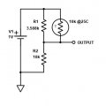
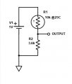
Here is a simple linearization using one resistor in parallel. For R1, use 3.6kΩ.
Use whatever supply voltage you wish. Just scale the output voltage accordingly.

thermistor_linear.jpg
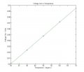
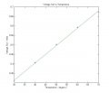
Here is the Voltage Output vs Temperature for the range 30 to 70 °C.


MF58_10k_linear.jpg
 

Thread Starter

q12x

Joined Sep 25, 2015
2,227
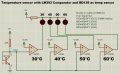
This is the cct I used in reality with my LM393.
I probed (the Signal line) initially with my osciloscope and nothing was changing so I switch to my DMM.
1724771962958.jpg
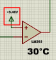
This is where I play with resistor volt-div in reality. The V numbers on the (+) inputs are from the simulator to make it work. Not from reality.
1724820142554.png
- - -
The result voltages are way too small and close to each other. In a way, the change is so small that is equivalent with the simulation change in Voltage if you notice it (the V on the (+) ). I believe....I need to amplify?!? this signal? maybe? - here Im not very sure how to increase that 670mV into 3.67V? .. or lower that (+) down to 670mV. Hmmmmmmm. Im thinking adding an opamp on the Signal line to rise its voltage.
Now I wish I had 3 or 4 decimals after 0. on my DMM. Huuuummmm.
Results in reality w DMM for V on Signal line:
670mV@34*C (0.67)=DMM reading
660mV@44*C (0.66)
630mV@54*C (0.63)
600mV@64*C (0.60)
 
Last edited:

Thread Starter

q12x

Joined Sep 25, 2015
2,227

Ian0

Joined Aug 7, 2020
13,158
Did you hunt for my shifting problem? when you raise up the temp collect the temp on paper from your electronic thermometer and when you let it cool also collect it. See if is a difference, if you have my shifting problem and how many *C apart they are.
Yes - we all know exactly what your shifting problem is, but you are not willing to accept the explanation.
 

Alec_t

Joined Sep 17, 2013
15,132
If I still get a shifting problem, then.... its something wrong with my cct or something very clever in my digital thermometer .....
..... or a problem with the way you are conducting your experiments. Use a water/oil bath as has been mentioned and I suspect the 'drifting' will diminish or disappear.
 

ag-123

Joined Apr 28, 2017
294
I did my thermistor this way
https://forum.allaboutcircuits.com/...-temperatures-using-cheap-thermistors.202688/
if you have sensor wires any longer than say 2cm/1inch (even 2cm probably matters) it would be an antenna and pick up radio waves. I've seen 'noise' on a long sensing wire that are probably radio waves and the radio waves alone are > 0.5 v (without amplification received on the ADC) ! (after all microcontrollers are SDR right?). A way to fix that is to use a large capacitor try 10-100 uF between the supply e.g. vdd and gnd at the sensor / thermistor. I did that it works wonders, the radio waves received practically *disappeared*, I get pure thermistor signal, no noise.

I didn't bother with linearization, I worked the Steinhart–Hart equation
https://en.wikipedia.org/wiki/Steinhart–Hart_equation
I get an R(thermistor) plug values and get temperature from there
oh it seemed a log amp can be made this way
https://www.tutorialspoint.com/line..._applications_log_and_anti_log_amplifiers.htm
so I'd guess with some clever (op amp) circuits, it may be after all possible to make a truly linear thermistor measurer, i.e. work the Steinhart–Hart equation in complete analog fashion.

In my circuit, I used a BJT as an amplifier, I think I achieved a precision (not necessary accuracy) of 0.1 deg C by virtue of the amplified / expanded range.
https://forum.allaboutcircuits.com/...-temperatures-using-cheap-thermistors.202688/
 
Last edited:

dl324

Joined Mar 30, 2015
18,405
I probed (the Signal line) initially with my osciloscope and nothing was changing so I switch to my DMM.
A scope isn't the appropriate tool to resolve such small differences.
The result voltages are way too small and close to each other.
Why did you remove the amplifier I used? Your circuit will never work.

Why are you using a 5V supply? The reference voltages you're using are too close to the maximum input voltage with a 5V supply.
 

dl324

Joined Mar 30, 2015
18,405
I breadboarded this circuit and checked it with a water bath of about 40C:
LM339Thermometer.jpg
As expected, the first 2 LEDs turned on. I let the water cool and it had to get down to 38C before the second LED would turn off. I didn't bother using a voltage divider to get more resolution on the set points.

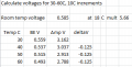
To check the results, I measured the actual gain of the amplifier (5.66). The second BC547B junction was 0.585 at 18C.

I adjusted R14 to get 3.16V at the top of the voltage divider. I replaced R9 with a 220k resistor and a 100k pot and adjusted the pot to get 2.79V at pin 10 of the LM339. I didn't have a 10uF cap handy, so I used a 1uF cap for C1. I used a twisted #24 pair to connect the transistor.

The voltage on the wiper in the schematic was before I fine-tuned parameters.

My calibration data:
1724870837637.png
 
Last edited:

Thread Starter

q12x

Joined Sep 25, 2015
2,227
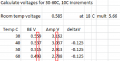
So LM358 opamp is helping increasing the measured voltage. Very good.
I noticed that BE_V is 2 decimals changing after 0. while after amplification, on your opamp LM358 output, we get 1 decimal after 0. That is 10 times (rounded) better result.
1724887794673.png
I have a question. - On the AMP V we have 100mV (or 0.1V) change, mostly (or that deltaV -0.125 that you mention, where "delta" means change; we are swimming in deep math here). Can we change it to be 200mV or 300mV or 400mV? A bit bigger than 100mV. My guess from the back of the yard is by changing R2 and R3 for (-) input on LM358. Its the only components we can really tweak, haha.
Very interesting results mister @dl324 ! I like it!
I will try your cct today and see what I will get.
 

twister007

Joined Feb 29, 2012
93
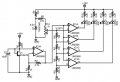
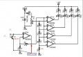
I had some time and breadboarded this circuit:
View attachment 330081
I couldn't find any LM3914, so I used LM3915.

I used my hot air tool on the transistor and observed the voltage changing with temperature. I heated the transistor enough to go off the scale (lowest voltage determined by R6). Since LM3915 isn't linear, I didn't bother to try to calculate actual temperatures.
Can you post a corrected schematic, so I can download it?
 

dl324

Joined Mar 30, 2015
18,405
Can we change it to be 200mV or 300mV or 400mV?
You can make it anything you want - within reason. But 125mV is more than large enough for the comparators to resolve.
My guess from the back of the yard is by changing R2 and R3 for (-) input on LM358. Its the only components we can really tweak
That changes the gain of the opamp (in a circuit that I'll post later, I made the gain 10.09 to make it easier to do mental math).

You also need to change the voltage divider, R4, R5, and the zener voltage.
 

Thread Starter

q12x

Joined Sep 25, 2015
2,227
Oook, So I jumped into my testing chair and I made your cct.
I did literally forgot to put 2 components though, but they turn out not that essential.
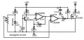
Here is the cct I used: I used exactly 10V and exactly the same values you used there. Excepting the LED's resistors.
With that 220k exception and also the 2 other components I forgot.
I also used BD139 since its having a better heat sink area.
1724870837637_LM339Thermometer_q12.jpg
- I did insert a 220k to 10V rail connected to (+) input, like in your cct, and the voltage jumped to 4V but the reading was the same, in the sense that it was changing 100mV per each 10*C. The only difference it was showing 4 instead of 2. I also believe that 10uF cap is adding a ton of delay. Why did you add it there? Although the signal wire from tr to (+) input was exceptionally sensitive to my fingers, the leds were flickering very visible when I was near or toughing it. Probably that's why you added that cap? Hmmm. I didn't try it yet.
- I also forgot my 1R50W resistor heater a bit too long and it raised to 80*C this time, so I go with it and measured everything. I'm glad I did because it turns out it is a faster reading and changing in temp at 60,70,80; while is way more slower change at 30,40,50,60. I did the temp reading for entire range though.
There is some shifting problem but is minimized now and I think it is good enough.
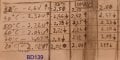
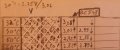
- The LED's did not switched on and off though! They were dimming in and out. So, I leave this problem aside for the moment and concentrated only on the Voltage reading to check if its stable on rising temp and lower temp. You can see the arrows drawn on paper. This what they signifies.
- A very important detail... at the very start of the experiment, when I first started the heating and reading, you see that first column in the left. Those readings are off with 10*C from the rest of the columns in the right. This means... that we have to leave some waiting time between the first read and the usual reading. Something like 30s to 1min waiting time after powering and then, starting to gather the informations.
1724870837638_20240829_043338.jpg
- Now pay attention to the last column, on the right. you see that 1.99V for the 80*C. It should have be 2.02V. Its 1.99 there because the heating element got to 85*C while in the first column when it got to 2.02V or the 3rd with 2.00V It stopped very close to 80*C. The entire column got influenced !
- Does your LED's lit up at 30,40,50,60? or just random or dimming like mine here?
- - -
- Another quick experiment, I raise it very close to 50*C and I got 2.40V I let it cool down to 35 then up again to 50 and again, I got 2.40V. Instead of 2.33V. Very interesting, right? See? this is my shifting problem. Hemmm. Its not that big, but it is big for the comparator.
 
Last edited:

dl324

Joined Mar 30, 2015
18,405
I also used BD139 since its having a better heat sink area.
You can't use any transistor. Even transistors of the same type have different voltages. I've used BC547B's and they all had different junction voltages at room temp (17-18C).

You'll have to tweak the circuit for the junction voltage of the transistor you use.

The opamp will amplify the junction voltage by 5.7 (subject to the actual resistances used). I measured the gain of my circuit to be 5.66.

The room temperature junction voltage will affect the set points you need for the opamps.
Does your LED's lit up at 30,40,50,60? or just random or dimming like mine here?
Mine lit sequentially as the temperature went up. They went out sequentially as the temperature went down. The LEDs to fade/brighten about the trip voltage. I considered that to be an unexpected feature.

Try using a 1uF cap instead of 10uF. I didn't have 10uF handy, so used 1uF.

Try putting a 0.1uF cap across the power on the comparators to see if that helps with the flickering.
 

Thread Starter

q12x

Joined Sep 25, 2015
2,227
Ok, I did the test this time with a BC548 and 1uF.
The Voltage jumped a bit compared to BD139 but really is the same deal after all, about 100mV difference between 10*C levels.
The LED's in my cct are not dimming anymore, thanks to that 1uF cap. Very interesting! Although I tested with 10uF and I left this 1uF in the end, and when the cct is first starting, my DMM reading at 32*C is slowly rising up from 0V up to 2.86V thanks to that capacitor there. So its a useless delay like I said originally, without testing. BUT! it is correcting the LEDs dimming for some reason. They either stay on or off. And nothing in between like before. But they are still very random lighting On or Off. I turn the 1k POT but that is good to set the minimum limit when the first led to light on. And it is shifting it correctly, but the leds are not properly responding to when is 40 or 50. They randomly lit On or Off, literally. I start to think maybe my LM393 is f*up???? I did test it originally with 1 pot and 2*1k and everything was ok. Hmmmm, very strange.
1724870837640_20240829_043339_2.jpg1724870837637.png
Its actually very close to your values with your BC547 !
 
Last edited:

dl324

Joined Mar 30, 2015
18,405
After fiddling with that water bath to make temperature measurements, it finally dawned on me that I could use a transistor temperature sensor to heat a power resistor to a specific temperature. (This is essentially the circuit I would have used for my well/chicken heaters.)
resistorHeater2.jpg
Initially I chose a 10 ohm 100W resistor to limit the current in the breadboard and to give the heat source some thermal mass. I found through experimentation that that was causing problems with overshoot (and possibly undershoot). The temperature would continue to rise after the MOSFET was turned off. And the 1A in the resistor was causing a 0.1V voltage drop in the power leads, which was enough to perturb the set voltage, so I switched to using a different power supply. Then I experimented with smaller wattage resistors before settling on 33 ohms/2W. I also found that my DVM reads +4C (by putting the probe in the ice bath).

With such a low current in the power resistor, I could switch back to a single supply. I just haven't bothered...

So, I started over and measured junction temperature at 0C (in an ice bath). From that value I calculated junction voltage at various temperatures (5 degree increments except for around room temp; I calculated 17, 18, 19 C). Using my table, I set the comparator voltage for 25C. The circuit worked as expected and the DVM indicated 29-30C, which corrected is 25-26C.

My DVM accuracy is supposed to be +/- 3digits plus 1% of the reading. It appears that my meter is a bit worse than that.

I'm using an opamp as a comparator, but it's not an issue in this case because a slow comparator is fine.

The transistor is connected to the circuit with some twisted pair. For testing, I taped the flat face of the transistor against the power resistor with electricians tape. I held the temperature probe from the meter on the resistor body near the transistor.

I used 1% resistors for the amplifier. Calculated gain is 10.09x, actual gain is 10.13x. I'm thinking about using a pot to get the gain to be 10 so I can do mental arithmetic.

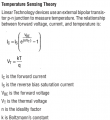
We have a bit of a chicken and egg scenario here due to measurement accuracy. You don’t trust your thermistors and now you have to consider the accuracy of your temperature meter. You could use this circuit to heat your thermistors to a certain temperature. But, to use transistors, you have to accept that the junction voltage changes by 2.2mV/C. And, how can you verify anything if your thermometer accuracy isn't known.

And I'm trusting my HP bench meter that hasn't been calibrated in decades...
 
Last edited:
Top