Technics SU VX-800 with blown components (another one)

Thread Starter

alprampo

Joined May 29, 2026
51
Good evening!


Replaced the following components:

  • Q507
  • C426
  • R505
  • R506
  • Q429 (found bad and replaced as well)
I powered the amp on using the incandescent lamp in series. Initially, the lamp glowed brightly and then dimmed, which is normal. After cycling power a couple of times to check if the relay would engage, the lamp went out completely and the main power switch popped open.

There was no smoke and no hot components.

When I checked the bulb, I found that its filament had broken. It seems strange to me that the amplifier could blow the bulb, since even a severe short circuit in the amp should just make the lamp burn at full intensity rather than burn out.

All internal fuses on the amp are still OK. Unfortunately, that was my last incandescent bulb, and they are very hard to find locally now as only LEDs are available.

Is there any static check I can perform next before sourcing another bulb?
Thanks!
 

Thread Starter

alprampo

Joined May 29, 2026
51
Edit: Upon double-checking, the test bulb is actually OK!

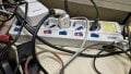
I realized that the main power switch popped because of an internal fault in the illuminated indicator bulb inside the power strip (multi-plug) switch I was using to toggle power. That indicator light was working before, but it is now completely off.

What do you think?

1790109403068.jpeg
thanks!
 

Thread Starter

alprampo

Joined May 29, 2026
51
For the time being, get another power bar to power the amplifier.
You can trouble shoot the bad power switch later.
after replacing following components:

  • Q507
  • C426
  • R505
  • R506
  • Q429
The amplifier is now back to its previous state and has entered normal operating mode (protection relay engaged), with no DC offset at the speaker outputs for protection circuit to be activated.
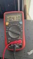
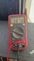
measurements on R513 show less voltage than required:

1790242398112.jpeg
1790242429546.jpeg


The reading on TP501 remains the same whether the speakers are turned ON or OFF:

  • Across + and - terminals: It shows a negative voltage around -22 mV, but it's very unstable. With the multimeter set to DC mV, the reading starts around 18 mV and fluctuates wildly up to 200 mV. I actually had to place my fingers across the multimeter probe tips just to get any kind of stable reading!
  • + terminal to ground: 25 mV DC
  • - terminal to ground: 4 mV DC
Thanks!
 

MrChips

Joined Oct 2, 2009
35,225
All your voltage readings are ok.
Do the 1 kHz sine wave input test with no speakers.
Start with the VOLUME CONTROL at 0 and gradually increase it. Do not exceed the mid-point.
Look at the speaker terminal using the oscilloscope, always on DC.
 

Thread Starter

alprampo

Joined May 29, 2026
51
All your voltage readings are ok.
Do the 1 kHz sine wave input test with no speakers.
Start with the VOLUME CONTROL at 0 and gradually increase it. Do not exceed the mid-point.
Look at the speaker terminal using the oscilloscope, always on DC.
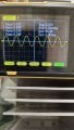
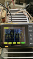
The signal looks clean, i guess...
At 1V
1790261249994.jpeg

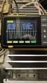
£V
1790261296036.jpeg

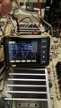
and still perfect at mid volume 7.3 V
1790261401026.png
Thanks
 

MrChips

Joined Oct 2, 2009
35,225
Repeat the 1 kHz sine wave test, starting with the VOLUME CONTROL at 0 and slowly turning up the volume. Do not test at full power output. This time, connect the loudspeaker to the speaker output.

If you have a 1000 μF or higher capacitor, you can put this in series with the loudspeaker to prevent blowing the loudspeaker if something goes wrong.

If this test passes, then you can try music audio input.
 

Thread Starter

alprampo

Joined May 29, 2026
51
Repeat the 1 kHz sine wave test, starting with the VOLUME CONTROL at 0 and slowly turning up the volume. Do not test at full power output. This time, connect the loudspeaker to the speaker output.

If you have a 1000 μF or higher capacitor, you can put this in series with the loudspeaker to prevent blowing the loudspeaker if something goes wrong.

If this test passes, then you can try music audio input.
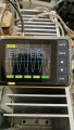
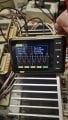
I think the test on speaker output passed:
1790277801709.jpeg


So I played some music, and...

The left channel started working! I'm really happy!

The sound is clean, though the output level is quite low relative to the volume knob position. Could this lower volume be due to the missing pair of power transistors?

I let the music play for about 20 minutes, and all the components remained completely cool to the touch!

Thanks!
 

MrChips

Joined Oct 2, 2009
35,225
12.8 Vpp is 6.4 V amplitude = 4.5 Vrms
If your loudspeaker is 8 Ω impedance, this is an output of about 2.5 W which ought to be loud!

Don't worry about the missing pair of transistors.
Work on the RIGHT channel now that you have experienced how to get one channel working.
 

Thread Starter

alprampo

Joined May 29, 2026
51
12.8 Vpp is 6.4 V amplitude = 4.5 Vrms
If your loudspeaker is 8 Ω impedance, this is an output of about 2.5 W which ought to be loud!

Don't worry about the missing pair of transistors.
Work on the RIGHT channel now that you have experienced how to get one channel working.

Hi everyone,

I've been working on the right channel for a while now, but unfortunately with no success...

Here is a summary of the parts I have replaced so far:

  • Q508, Q510 (Power transistors — replaced as they could be fakes)
  • Q428, Q430 (Driver transistors): Swapped out the eBay replacement pairs (2SA1535 / 2SC3944) for genuine 2SA1306 and 2SC3298 pulled from a known working unit.
  • Q402, Q404: Replaced them back. (At the start of this repair, they were replaced with newer 2SC2632 instead of 2SC2631, and 2SA1124 instead of 2SA1123).
  • IC402: Replaced again (it had exploded during the initial failure).
Current Issue / Symptoms:

  • Without a load (no speaker connected): The audio signal looks completely clean on the scope.

1790535304504.jpeg

With a load (speaker connected): Severe signal clipping and distortion occur.
  • 1790535341060.jpeg


  • Tracing with the scope, i find the distortion originates right at IC402:
    • Pin 5: Signal is clean. with and without load

      1790535404322.jpeg

    • Pin 6:with speaker
    • 1790535490097.jpeg

  • Pin 6 without speaker

    1790535595998.jpeg
    • Pin 7 no speaker
    • 1790535664772.jpeg


connecting speaker VPP raises to 13.95
1790535750627.jpeg

Adjusting view on scope:
1790535790543.jpeg
Any ideas on what might be causing IC402 to distort as soon as a load is applied?

Thanks in advance for any insights!
 

MrChips

Joined Oct 2, 2009
35,225
Why are you looking at IC402 pins 5, 6, and 7? These are on the LEFT channel.

Whenever you see a square wave signal, this represents overload. Reduce the VOLUME level to below overload level.
 

Thread Starter

alprampo

Joined May 29, 2026
51
Thanks Mr. Chips

I took measurements on pins 5, 6, and 7 of IC402, since even component numbers should correspond to the right channel.
Additionally, for reasons unknown to me, looking at the schematic it appears they chose to use pins 1, 2, and 3 on IC401 instead.
One thing I don't quite understand is the voltage increase when the speaker is connected. I didn't change the volume pot position, which is set around 9 o'clock—certainly not high enough to cause such severe distortion.
Thanks!
 

MrChips

Joined Oct 2, 2009
35,225
Ignore testing IC402 for now.
Start by looking at the signals at TP502 (+) and (-) with no speaker attached.
Do not increase VOLUME level beyond saturation at the test points.
 

Thread Starter

alprampo

Joined May 29, 2026
51
Sorry for the silence. I had to figure out how to recalibrate my oscilloscope, as it was no longer displaying anything readable.
I took measurements on TP502, and the signal (with the speaker off) is clean.
Between -and ground

1790792708773.jpeg

+ and ground
1790792746875.jpeg

I also repeated the test on R514 that you asked me to perform previously on both sides of R513 (the resistor between the emitters of the driver transistors and the bases of the power transistors). It measures under 500mV, which is more or less the same as the left channel.
but both values are positive
+328mv and +364mv

Thanks!
 

MrChips

Joined Oct 2, 2009
35,225
Looks good. Do the same test with the loudspeaker connected.
Start with the VOLUME control set to 0 and increase gradually. Stop increasing if the signal saturates.
 

Thread Starter

alprampo

Joined May 29, 2026
51
Saturation occurs immediately.
At 0.15V, the negative half-cycle is already clipped, and the positive half-cycle clips after just a small turn of the knob.
Additionally, the waveform is no longer centered on the scope screen. Is this an oscilloscope calibration issue, or is the circuit unbalanced due to a faulty component?

1790799881480.jpeg

1790799930098.jpeg

with no speaker:
1790800179668.jpeg
thanks
 

MrChips

Joined Oct 2, 2009
35,225
I assume that you have Q516 and Q518 removed from the circuit.

Are Q508 and Q510 replacements?
Do you have another fresh pair you can try?
 

Thread Starter

alprampo

Joined May 29, 2026
51
I assume that you have Q516 and Q518 removed from the circuit.
Correct, the sockets are empty.
Are Q508 and Q510 replacements?
Yes, they are replacements, but sourced from AliExpress. The ones currently working on the left channel are from AliExpress too, but they came from two different vendors—so maybe one batch was good and the other bad. Back in 2025, I wasn't aware of many things I'm just learning now, including the issue with counterfeit components.
Do you have another fresh pair you can try?
I can either swap them with the left channel ones or these that are 100% genuine pair to try.

1790801463869.jpeg
May be it's time to buy modern replacement from a reliable seller such as RS components, digikey or Mouser
https://eu.mouser.com/en/ProductDetail/Toshiba/2SC5200NS1ES?qs=2kOmHSv6VfQbtmQk0KOp/w==
Consulting AI and google, it seems the 2sc5200N and it's complementary are a good choise.
What do you think about them?

If I'm not wrong when the transistor are connected in parallel, their HFE should be as similar as possible, so are enough 10 pieces of a kind to select best couples?
Thanks
 

Thread Starter

alprampo

Joined May 29, 2026
51
I replaced the output transistors with a pair of 2SC3280 / 2SA1301, but the issue remains unchanged.
1790845571069.jpeg
I also performed a test listening with headphones (using a wireless transmitter/receiver connected to the headphone jack):

  • With speakers OFF, the audio is completely clean.
  • The moment speakers are turned ON, the signal degrades and distorts immediately, exactly as described earlier.
 
Top