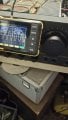
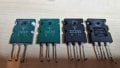
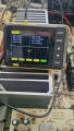
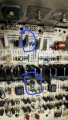
Technics SU VX-800 with blown components (another one)

Thread Starter

alprampo

Joined May 29, 2026
23
The signals at TP501 appear to be ok.
What does the signal look like at the loadspeaker output, with and without a loudspeaker connected?
The signal shape, with or without a speaker connected, doesn't change when set to a reasonable volume level. However, when playing actual music, the sound is still far from clean.

I can upload a video or audio clip so you can get a better idea of what it sounds like.


1789590688966.jpeg
 

Attachments

Thread Starter

alprampo

Joined May 29, 2026
23
Sine wave is perfect, sound itself as well, until mid volume
After half position sound is like vibrating or like a drill
While The music even at low level is like a woofer with foam gone
And before you ask, yes. Speakers are good.
Thanks
 

Thread Starter

alprampo

Joined May 29, 2026
23
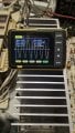
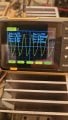
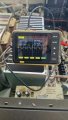
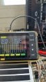
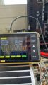
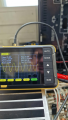
Here is what it looks like on the scope!
1789630165830.jpeg
Just to clarify, the distortion isn't a gradual buildup —it behaves more like a binary 0/1 toggle switch
Thank you
 

Pyrex

Joined Feb 16, 2022
542
I wonder how it can be that in such a not very long chain, the shape of the signal basically changes...

Check again the signal with the oscilloscope on the following components:
TP501
L501 on both ends
R555 on both ends
R557 on both ends
L503 on both ends
L551 on both ends
JK501

At which point did the signal go from a perfect sine wave to something messed up?
 

MrChips

Joined Oct 2, 2009
35,127
The oscilloscope view is indicating distortion in the negative half of the cycle.
To me, this suggests that Q509 is not receiving enough drive (assuming that Q515 and Q517 are removed from the board).
Two possibilities come to mind.
(1) VR403 needs tweaking
(2) Q509 is wonky.

Where did you buy your replacement transistors? Did you buy them from a reputable distributor?

To test DC balance, remove the sine wave input.
Measure DC voltages at TP501 (+) to GND and TP501 (-) to GND.
The measure between TP501 (+) and TP501 (-).

Also measure both ends of R513 with respect to GND.
 

MrChips

Joined Oct 2, 2009
35,127
Looking back at your recent oscilloscope photos, I see that your input is set to AC.
Change this to DC. We need to see the DC offset in your signals.
 
Top