Technics SL-PJ1 CD player

Thread Starter

Rabbitbreth

Joined Jan 22, 2019
188
Hiya,

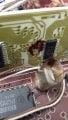
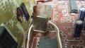
I am struggling to identify the value of this resistor from a old Technics CD player . ( SL-PJ1)

The problem is the RH channel has gone ..barely audible . I replaced the blown resistor (R815) with what I thought it might be and the channel works again but its too loud and distorting , so I guess I need a higher resistance. To clarify , the new resistor in the pic is the wrong value and the blown one looks like it has one red and 2 x blue code .

Sorry I dont have any schematic but I'm hoping someone could identify or suggest a resistor value to try .

Thank you 20260309_165211.jpg20260310_113213.jpg20260310_134214.jpg
 

panic mode

Joined Oct 10, 2011
4,864
google AI thinks it should be 22k. i think i see the an orange band so that value is plausible. it would be better if the old resistor was wiped clean using paper tissue.
R816 is 33k. i would probably try the same. to be sure you can lookup service manual.

https://www.turntableneedles.com/Te...r_Instant_PDF_Download_English_Service_Manual

one red and two blue is backwards.
two blue(ish) and one red(ish) is likely to be:

5.6k (green blue red)
6.8k (blue gray red)
56k (green blue orange)
68k (blue gray orange)

one that is presently in place seem to be 1.5k (brown green red)
 
Last edited:

twohats

Joined Oct 28, 2015
606
Hi,
If you look up the datasheet for I.C 805 you may be able to determine left and right channels.
R 816 could be one channel and R 815 could be the other channel. So try 33k as suggested by panic mode.
Good luck ...........
 

Thread Starter

Rabbitbreth

Joined Jan 22, 2019
188
google AI thinks it should be 22k. i think i see the an orange band so that value is plausible. it would be better if the old resistor was wiped clean using paper tissue.
R816 is 33k. i would probably try the same. to be sure you can lookup service manual.

https://www.turntableneedles.com/Te...r_Instant_PDF_Download_English_Service_Manual

one red and two blue is backwards.
two blue(ish) and one red(ish) is likely to be:

5.6k (green blue red)
6.8k (blue gray red)
56k (green blue orange)
68k (blue gray orange)

one that is presently in place seem to be 1.5k (brown green red)
Hiya . Thanks for your reply . I have tried to clean the old resistor but its pretty mucky ..only a blue and red or orange is all I can see . will try another pic perhaps with another phone . will try another 33k and see what happens . cheers for that
 

Thread Starter

Rabbitbreth

Joined Jan 22, 2019
188
Hi,
If you look up the datasheet for I.C 805 you may be able to determine left and right channels.
R 816 could be one channel and R 815 could be the other channel. So try 33k as suggested by panic mode.
Good luck ...........
will try a 33k . thanks alot for your input .
 

Thread Starter

Rabbitbreth

Joined Jan 22, 2019
188
well thanks a lot for fixing me up Mr Chips .
Hi again ,

I ordered some resistors . 6.8 k ...blue ones ...1/4 watt . are they supposed to be 2w ? very loud and distorted the RH signal is again .
Perhaps something else is blown do you think ?
MF25 1/4W Resistors 1% All Values (0R-1K-10M) 1
Thank
 
Last edited:

0ri0n

Joined Jan 7, 2025
160
I ordered some resistors . 6.8 k ...blue ones ...1/4 watt .
1/4W is fine. R815 is identical to R803 and both should be 6k8.


very loud and distorted the RH signal is again .
Only the R-channel is loud and distorted?

Both channels are fed from the same PCM53 mono 16-bit DAC (IC801), followed by the L/R deglitching, lowpass filter modules and output buffers.

If only one channel is bad then look at either the 4053 MUX switch (IC805), active lowpass filter module (LPF802) or associated op amp LM833 (IC806).

A voltmeter and/or a scope would be nice to have. Start with checking the +/-5V and +/-15V supply rails for these ICs.
 

Thread Starter

Rabbitbreth

Joined Jan 22, 2019
188
1/4W is fine. R815 is identical to R803 and both should be 6k8.


Only the R-channel is loud and distorted?

Both channels are fed from the same PCM53 mono 16-bit DAC (IC801), followed by the L/R deglitching, lowpass filter modules and output buffers.

If only one channel is bad then look at either the 4053 MUX switch (IC805), active lowpass filter module (LPF802) or associated op amp LM833 (IC806).

A voltmeter and/or a scope would be nice to have. Start with checking the +/-5V and +/-15V supply rails for these ICs.
ok/ will get on that . thank you for input . YES only the RH channel is loud and distorted . LH is fine .

heres something that might be trouble . any thoughts?? pics incoming
 

Attachments

Last edited:

MrChips

Joined Oct 2, 2009
34,626
The standard procedure for trouble-shooting something of this nature is with an oscilloscope. If you do not have access to an oscilloscope, there is audio tracing technique you can use with a PC amplified speaker.

In your case, I assume that you already have an external amplifier into which the CD player is connected.

Unplug the LEFT and RIGHT channels into the amplifier.
Using the LEFT channel into the amplifier, test both LEFT and RIGHT channel of the CD player outputs.
Repeat using the RIGHT channel into the amplifier.
Confirm that the problem is with the RIGHT channel of the CD player and not that of the amplifier.

Get a 10 μF electroytic capacitor. Voltage rating is not critical, 16-63 V will do fine.
Use either channel of the working amplifier as your audio test instrument. Use the capacitor as your probe, wired in series with the tip of the connector leading into the amplifier. Alligator jumpers are good for this.
Plug in the unused channel in order to make a common ground connection.

Look at the circuit schematics shown below.
LEFT channel audio goes from LPF801 pin-6, IC803 pin-1, IC804 pin-1, C808, R813.
RIGHT channel audio goes from LPF802 pin-6, IC806 pin-1, C813, R822

Probe along these points and try to identify a difference in the audio sound level and quality. You should be able to find the problem here somewhere along the faulty RIGHT channel.

Start with the jumper J between C808 and R813 on the LEFT channel, and jumper J between C813 and R822 on the Right channel.

I have no idea of the purpose of IC804(1/2). But this is irrelevant.

Technics SL-PJ1 CD audio circuit.jpg


Technics SL-PJ1 CD audio circuit PCB.jpg
 

Thread Starter

Rabbitbreth

Joined Jan 22, 2019
188
The standard procedure for trouble-shooting something of this nature is with an oscilloscope. If you do not have access to an oscilloscope, there is audio tracing technique you can use with a PC amplified speaker.

In your case, I assume that you already have an external amplifier into which the CD player is connected.

Unplug the LEFT and RIGHT channels into the amplifier.
Using the LEFT channel into the amplifier, test both LEFT and RIGHT channel of the CD player outputs.
Repeat using the RIGHT channel into the amplifier.
Confirm that the problem is with the RIGHT channel of the CD player and not that of the amplifier.

Get a 10 μF electroytic capacitor. Voltage rating is not critical, 16-63 V will do fine.
Use either channel of the working amplifier as your audio test instrument. Use the capacitor as your probe, wired in series with the tip of the connector leading into the amplifier. Alligator jumpers are good for this.
Plug in the unused channel in order to make a common ground connection.

Look at the circuit schematics shown below.
LEFT channel audio goes from LPF801 pin-6, IC803 pin-1, IC804 pin-1, C808, R813.
RIGHT channel audio goes from LPF802 pin-6, IC806 pin-1, C813, R822

Probe along these points and try to identify a difference in the audio sound level and quality. You should be able to find the problem here somewhere along the faulty RIGHT channel.

Start with the jumper J between C808 and R813 on the LEFT channel, and jumper J between C813 and R822 on the Right channel.

I have no idea of the purpose of IC804(1/2). But this is irrelevant.

View attachment 364676


View attachment 364681
wow. ok ..let the healing begin . I dont have a scope but I have a cap probe I made up from my last adventure .
My amp is fine and is hooked up to another CD player . sounds fine .

will have a go and let you know . thanks for the schematics and direction.
 

0ri0n

Joined Jan 7, 2025
160
heres something that might be trouble . any thoughts?? pics incoming
That's the LSI module that controls the deglitching/S&H stages and drives the Burr-Brown DAC. Looks nasty but probably nothing wrong with it as one channel is working. You could try doing some cleaning without damaging the module.
 

Thread Starter

Rabbitbreth

Joined Jan 22, 2019
188
That's the LSI module that controls the deglitching/S&H stages and drives the Burr-Brown DAC. Looks nasty but probably nothing wrong with it as one channel is working. You could try doing some cleaning without damaging the module.
ah . is that what is !!. great to know at last . not sure what actually melted ..or if it's just glue ..will have a closer look ,try take that clear cover off and will clean it up afterwards ...carefully . thanks for that
 
Top