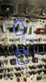
Technics SU VX-800 with blown components (another one)

Thread Starter

alprampo

Joined May 29, 2026
29
The signals at TP501 appear to be ok.
What does the signal look like at the loadspeaker output, with and without a loudspeaker connected?
The signal shape, with or without a speaker connected, doesn't change when set to a reasonable volume level. However, when playing actual music, the sound is still far from clean.

I can upload a video or audio clip so you can get a better idea of what it sounds like.


1789590688966.jpeg
 

Attachments

Thread Starter

alprampo

Joined May 29, 2026
29
Sine wave is perfect, sound itself as well, until mid volume
After half position sound is like vibrating or like a drill
While The music even at low level is like a woofer with foam gone
And before you ask, yes. Speakers are good.
Thanks
 

Thread Starter

alprampo

Joined May 29, 2026
29
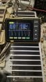
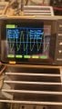
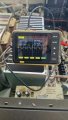
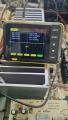
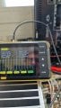
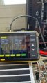
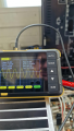
Here is what it looks like on the scope!
1789630165830.jpeg
Just to clarify, the distortion isn't a gradual buildup —it behaves more like a binary 0/1 toggle switch
Thank you
 

Pyrex

Joined Feb 16, 2022
546
I wonder how it can be that in such a not very long chain, the shape of the signal basically changes...

Check again the signal with the oscilloscope on the following components:
TP501
L501 on both ends
R555 on both ends
R557 on both ends
L503 on both ends
L551 on both ends
JK501

At which point did the signal go from a perfect sine wave to something messed up?
 

MrChips

Joined Oct 2, 2009
35,157
The oscilloscope view is indicating distortion in the negative half of the cycle.
To me, this suggests that Q509 is not receiving enough drive (assuming that Q515 and Q517 are removed from the board).
Two possibilities come to mind.
(1) VR403 needs tweaking
(2) Q509 is wonky.

Where did you buy your replacement transistors? Did you buy them from a reputable distributor?

To test DC balance, remove the sine wave input.
Measure DC voltages at TP501 (+) to GND and TP501 (-) to GND.
The measure between TP501 (+) and TP501 (-).

Also measure both ends of R513 with respect to GND.
 

MrChips

Joined Oct 2, 2009
35,157
Looking back at your recent oscilloscope photos, I see that your input is set to AC.
Change this to DC. We need to see the DC offset in your signals.
 

Thread Starter

alprampo

Joined May 29, 2026
29
I wonder how it can be that in such a not very long chain, the shape of the signal basically changes...

Check again

At which point did the signal go from a perfect sine wave to something messed up?
Shall I measure as usual
I wonder how it can be that in such a not very long chain, the shape of the signal basically changes...

Check again the signal with the oscilloscope on the following components:
TP501
L501 on both ends
R555 on both ends
R557 on both ends
L503 on both ends
L551 on both ends
JK501

At which point did the signal go from a perfect sine wave to something messed up?
Thanks for reply
Shall I measure with 150mv 1Khz as usual with oscilloscope set to AC?
Between points above and GND.
Thanks
 

Thread Starter

alprampo

Joined May 29, 2026
29
The oscilloscope view is indicating distortion in the negative half of the cycle.
To me, this suggests that Q509 is not receiving enough drive (assuming that Q515 and Q517 are removed from the board).
Two possibilities come to mind.
(1) VR403 needs tweaking
(2) Q509 is wonky.

Where did you buy your replacement transistors? Did you buy them from a reputable distributor?

To test DC balance, remove the sine wave input.
Measure DC voltages at TP501 (+) to GND and TP501 (-) to GND.
The measure between TP501 (+) and TP501 (-).

Also measure both ends of R513 with respect to GND.

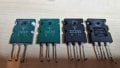
The transistors came from AliExpress, so I'm really sorry—I definitely didn't mean to waste your time!

I can replace them with a couple of 100% genuine 2SA1301 and 2SC3280 transistors.

1789676663438.jpeg
1789676710560.jpeg
1789676752650.jpeg
I just hadn't installed them yet because they were pulled from another amp and I didn't want to risk damaging them, plus I don't have enough to replace all of them.

Should I repeat all the measurements with the oscilloscope set to DC coupling?

I will start tracing the signal on the live circuit: I'll inject a 1 kHz sine wave into the AUX input and follow the signal chain to pinpoint where it distorts or drops off as done previously in AC mode.
thanks
ALberto
 

Pyrex

Joined Feb 16, 2022
546
An amplifier that is working well will have a very small DC component, just fractions of a volt, so measure it with an oscilloscope in DC coupling mode.
 

Thread Starter

alprampo

Joined May 29, 2026
29
Hi Guys!
I repeated the tests using the AliExpress transistors for now. I won't replace any components until you tell me to do so.

I switched the test speaker to an old Acoustic Research AR12, which seems to produce different readings on the oscilloscope, likely due to a heavier/different load.

Here is the reading at TP501 (positive test point relative to ground) with the speaker OFF:


1789827230230.jpeg
Same with speaker on:
1789827353126.jpeg

TP501 - and ground. speaker on:
1789827443152.jpeg

while TP501 + and -
1789827515017.png

On R513
Left pin looking from front with speaker on
1789828397529.jpeg
on right pin :
1789828433899.jpeg
with speaker off:
1789828462859.jpeg
1789828485912.png
Thanks!
have a good weekend!
Alberto
 

Thread Starter

alprampo

Joined May 29, 2026
29
Good morning,

I connected the multimeter to TP501 while adjusting trimmer VR403. Since I wasn't seeing any voltage change on the meter, I kept turning it until something literally went up in smoke!

Well, I have to admit I might have made a stupid mistake by shorting the positive TP501 to ground... but I'm not entirely sure.

I cut the power immediately. At first glance, I couldn't see any obvious visual damage, but I haven't turned the unit back on.

[Edit: Just tested 2SC3182, and it is shorted the 2SA1265 seems to be OK.]

Another lesson learned the hard way! What else should I check first to assess the full extent of the damage?

Thanks!
 
Last edited:

MrChips

Joined Oct 2, 2009
35,157
Test Q507 and Q509.
Test Q501, Q503 and Q505.

After installing good transistors, measure the voltages at R513 with respect to GND.
We are looking for +0.5V at the emitter of Q503 and -0.5V at the emitter of Q505.
 

Thread Starter

alprampo

Joined May 29, 2026
29
Test Q507 and Q509.
Desoldered:
Q507 is broken
Q509 is good

Test Q501, Q503 and Q505.
Tested in circuit and they are good.

After installing good transistors, measure the voltages at R513 with respect to GND.

powering on the amp no longer goes in "Drive" mode
C428 is HOT and felt, I assume it's due to R506 open (cut for measuring)
1789932538973.png


While R505 is 7.8 ohm instead of 6.8 ohm
So I will check voltage below just after replacing these latest damages.


We are looking for +0.5V at the emitter of Q503 and -0.5V at the emitter of Q505.
Thanks!
 
Top