Technics SU VX-800 with blown components (another one)

Thread Starter

alprampo

Joined May 29, 2026
33
Good evening!


Replaced the following components:

  • Q507
  • C426
  • R505
  • R506
  • Q429 (found bad and replaced as well)
I powered the amp on using the incandescent lamp in series. Initially, the lamp glowed brightly and then dimmed, which is normal. After cycling power a couple of times to check if the relay would engage, the lamp went out completely and the main power switch popped open.

There was no smoke and no hot components.

When I checked the bulb, I found that its filament had broken. It seems strange to me that the amplifier could blow the bulb, since even a severe short circuit in the amp should just make the lamp burn at full intensity rather than burn out.

All internal fuses on the amp are still OK. Unfortunately, that was my last incandescent bulb, and they are very hard to find locally now as only LEDs are available.

Is there any static check I can perform next before sourcing another bulb?
Thanks!
 

Thread Starter

alprampo

Joined May 29, 2026
33
Edit: Upon double-checking, the test bulb is actually OK!

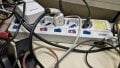
I realized that the main power switch popped because of an internal fault in the illuminated indicator bulb inside the power strip (multi-plug) switch I was using to toggle power. That indicator light was working before, but it is now completely off.

What do you think?

1790109403068.jpeg
thanks!
 

Thread Starter

alprampo

Joined May 29, 2026
33
For the time being, get another power bar to power the amplifier.
You can trouble shoot the bad power switch later.
after replacing following components:

  • Q507
  • C426
  • R505
  • R506
  • Q429
The amplifier is now back to its previous state and has entered normal operating mode (protection relay engaged), with no DC offset at the speaker outputs for protection circuit to be activated.
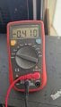
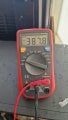
measurements on R513 show less voltage than required:

1790242398112.jpeg
1790242429546.jpeg


The reading on TP501 remains the same whether the speakers are turned ON or OFF:

  • Across + and - terminals: It shows a negative voltage around -22 mV, but it's very unstable. With the multimeter set to DC mV, the reading starts around 18 mV and fluctuates wildly up to 200 mV. I actually had to place my fingers across the multimeter probe tips just to get any kind of stable reading!
  • + terminal to ground: 25 mV DC
  • - terminal to ground: 4 mV DC
Thanks!
 

MrChips

Joined Oct 2, 2009
35,173
All your voltage readings are ok.
Do the 1 kHz sine wave input test with no speakers.
Start with the VOLUME CONTROL at 0 and gradually increase it. Do not exceed the mid-point.
Look at the speaker terminal using the oscilloscope, always on DC.
 

Thread Starter

alprampo

Joined May 29, 2026
33
All your voltage readings are ok.
Do the 1 kHz sine wave input test with no speakers.
Start with the VOLUME CONTROL at 0 and gradually increase it. Do not exceed the mid-point.
Look at the speaker terminal using the oscilloscope, always on DC.
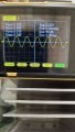
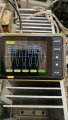
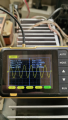
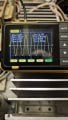
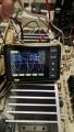
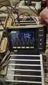
The signal looks clean, i guess...
At 1V
1790261249994.jpeg

£V
1790261296036.jpeg

and still perfect at mid volume 7.3 V
1790261401026.png
Thanks
 

MrChips

Joined Oct 2, 2009
35,173
Repeat the 1 kHz sine wave test, starting with the VOLUME CONTROL at 0 and slowly turning up the volume. Do not test at full power output. This time, connect the loudspeaker to the speaker output.

If you have a 1000 μF or higher capacitor, you can put this in series with the loudspeaker to prevent blowing the loudspeaker if something goes wrong.

If this test passes, then you can try music audio input.
 
Top