
Myron Steinberg 1
- Joined Aug 1, 2019
- 12
(?) That's a long time to be working on the problem.")
(?) That's a long time to be working on the problem.
So why did you ask the question about an analytical solution, since you apparently already know that?And I created many different filters including Butterworth 3rd order filters.
So why did you ask the question about an analytical solution, since you apparently already know that?

.png") That's the Circuit, i know came up with. I just have to calculate the input and output Impedances, to determine a Coupling capacitor for the usage of one Power supply.
That's the Circuit, i know came up with. I just have to calculate the input and output Impedances, to determine a Coupling capacitor for the usage of one Power supply.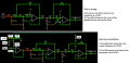
Where?Here is another possible circuit
.png") (actually without the blue selected wire )
(actually without the blue selected wire ).png")
Well actually the Vcc/2 lines all have to come from a divider anyway if this is to work off of a 24v supply only.MrAl,
This circuit has its +24V fed from a noisy switching power supply. In your new circuit you are feeding that noise directly into the inputs of the opamps.
My circuit had the Vcc/2 biasing filtered to remove the switching noise.
Oh, are you thinking that this lowpass filter circuit will not pass high frequency switching noise?
At the end of post #93. You dont see it?Where?

Here is another solution which doesnt required using unusual capacitor values...
[LATER]
I thought i should mention that if we change the 97k and 172k resistors slightly we can get a flatter response in the pass band, but we loose some sharpness in the cutoff region. We can also allow a little more overshoot (like maybe 5 percent) and get a sharper response.
I was able to get a flat response to within 0.1 percent but the response becomes somewhat less sharp. Allowing 3 percent overshoot the response sharpness is the same as the original circuit.

| Thread starter | Similar threads | Forum | Replies | Date |
|---|---|---|---|---|
|
|
Summing Amplifier Channel Isolation Problem | Analog & Mixed-Signal Design | 11 | |
| E | Summing amplifier | Homework Help | 11 | |
|
|
Ripples in square wave output of LM7171 high speed OpAmp. | Digital Design | 19 | |
| C | Summing Amplifier - Revisited | Analog & Mixed-Signal Design | 2 | |
| H | Non Inverting Summing Amplifier Design | Analog & Mixed-Signal Design | 34 |


