 Facebook
 Google
 GitHub
 Linkedin
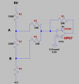
This is the first time i have used LTspice so the schematic may not be drawn conventionally but my problem or the thing i don't understand is when i make R4 110R , i get -1.14v at point A, -3.65v at point B and 3.11v output which in itself doesn't make any sense to me, if i make R4 2k, then i get 2.23v at point A, 1.15v at point B and -3.3v output which is perfect.
my negative probe is on v.ground (4.5v) for all readings
My question is why does the summing circuit not work with R4 = 110R? why doesn't the op amp give me the negative output from my two inputs?
The OPO7 by the op amp is there to stay, i can't delete it for some reason, LTspice won't let me.
my negative probe is on v.ground (4.5v) for all readings
My question is why does the summing circuit not work with R4 = 110R? why doesn't the op amp give me the negative output from my two inputs?
The OPO7 by the op amp is there to stay, i can't delete it for some reason, LTspice won't let me.
Attachments
-
 17.5 KB Views: 18
Last edited:


