Facebook
 Google
 GitHub
 Linkedin
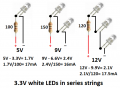
My circuit board LEDs (scale model) flicker instead of staying steady. A few do not light at all (but have lit before). Here's my set up and some mini history:
18 white LEDs (3.3 Vf, 20mA ea, total 360mA)
5V mini power brick (2000mA, 5V, 1A)
18 x 100 ohm resistors (1w) in parallel. Ohm's Law and resistor calculator say 85ohm
Connections soldered. Bad connections unlikely.
I first tried a 12v camera battery and a tiny buck board to get to 5V: LEDs came on dim and flashed once, then nothing. Disconnected and reconnected, dim flash on reconnection each time.
Switched to a wall wart, 5V, 1A. The LEDs came on bright but flickered often, almost flashing. Original 0.25watt resistors very quickly became soooper hot.
Switched to a mini power brick as above. Lights came on bright and steady, but one LED flickers like it's on a flasher circuit, and a few don't come one at all (they have lit before). New resistors 1watt, warm but OK. Tried full sized bricks, 11,000 and 20,000mA, same.
I'm no super genius, but I think maybe something is wrong. The circuit wiring is 2 layers of copper tape (4mm or 3/16th"), about 960mm or 3ft. All the resistors are grouped on a mini circuit board.
I don't know what is happening. I thought the wall wart would solve everything.