raspberry pi controlled capacitor charge start/monitor/stop

Thread Starter

gdarcan

Joined Jun 7, 2025
3
Hello;

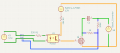
I'm learner/beginner and I'm trying to build a capacitor charging circuit. I burned one ADS1115 and one raspberry pi4 and I'm little scared. Once 30V went ADS1115 now I connected voltage divider around capacitor and mosfet. Are there anything crucially incorrect?

(In KiCad for simulating GPIO I put 3.3V DC source on the left. ADS1115 will be connected behind thru SDA/SCL/3.3V+/GND
Boost converter is taking input voltage from same battery 12V9Ah and outputs 55V)

1749335207422.png
 

Attachments

Ian0

Joined Aug 7, 2020
13,097
Where does the AD1115 get its supply from? Where is the 3.3V supply connected?
You need a gate-source resistor on the MOSFET to turn it off when the optoisolator switches off.
 

Thread Starter

gdarcan

Joined Jun 7, 2025
3
Where does the AD1115 get its supply from? Where is the 3.3V supply connected?
You need a gate-source resistor on the MOSFET to turn it off when the optoisolator switches off.
Thanks for replying...

ADS1115 is connected Raspberry, 3.3V, GND, SDA, SCL. I tested that section with jumper cables before and it's working fine. Previous design had common ground thru all components and ADS got 30V when mosfet is off and they burned together with RPI. It was working fine and measuring upto some voltage divided to max 5V precisely.

If gate/source resistor is the only missing part, then I'll proceed printing this :)
 

Thread Starter

gdarcan

Joined Jun 7, 2025
3
How are your two 0V connections interconnected?
I'm trying to figure out. At simulation I see 55V at A0 endpoint but I'm sure 'Im doing something wrong. I'm starting to realize that, ADS1115 A0 pin and gnd will act like probes of multimeter, right? Maybe spice models which I found for PC817 AND IRL540N are incorrect.

I think I found a method like this: I'll try with 5V instead of 55V to verify if I'm seeing divided voltage at A0 smth like 0.05 etc. and gradually increase it slowly. Also as I'm trying to figure out, I'll add a GND line from exit of capacitor to gnd of RPI (which is shared to ADS1115) (like probes of multimeter)
 
Top