Motor Control with push button Start, Stop and Emergency Stop.

Thread Starter

Back Beat Pat

Joined Oct 24, 2019
26
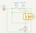
I have a 3 button control panel that would be more commonly used to control industrial equipment. It has a Start, Stop and Emergency Stop button layout as the image attached indicates. As a DIY project to control a project using a washing motor I have connected in different ways but not getting the desired control result. I have outlined the basis of my approach in the 2nd part of the image. What might be missing?Wiring Diagram.jpg
 

MaxHeadRoom

Joined Jul 18, 2013
30,593
Your method shoudl open the live conductor to the motor.
The second (RH) one will not work with a green N.O. PB.
It is used in the left hand circuit in order to engage the motor contactor.
You either need the typical E-Stop (PB) version or just use the red E-stop button.
 

crutschow

Joined Mar 14, 2008
38,401
For momentary push button control, you need a relay or contactor, connected as a latch (below).
The relay has a 240Vac coil.
B1 (Start) is a NO PB and B2 (Stop) is a NC PB.
For your application, the + (hot/live) and - (neutral) are the AC inputs.
Connect point C to the + input, with D going to the motor.

What do you see as the difference between the Stop and Emergency Stop in your control of the motor?
If the Emergency Stop switch can handle the motor current, then it could be put in series with the hot lead to the motor, to provide a stop independent of the relay position.

1761500271470.png
 

Thread Starter

Back Beat Pat

Joined Oct 24, 2019
26
Great detailed responses. I guess I was hoping to replicate the workings of an NVR switch with an Emergency Stop capability. I guess using the LA38 series button switches is not the way to go. Even the connection numbering is different on these switches like 11 and 12 & 23 and 24. Maybe it's just back to the three pin plug control for the moment.

Maybe confused myself thinking I could just replace the contactor in this video with the universal motor. https://youtube.com/shorts/uKUw19mzs10?si=2Qx98CvRENrJzOaH
 

MaxHeadRoom

Joined Jul 18, 2013
30,593
That video link content does not make sense. Does not show whether NC or NO SW/PB's ?
The norm is the typical E-Stop string as I show in the DWG.
Otherwise, you may as well just go with a simple ON/OFF Switch etc. and switch the motor direct?
 

Thread Starter

Back Beat Pat

Joined Oct 24, 2019
26
Otherwise, you may as well just go with a simple ON/OFF Switch etc. and switch the motor direct?
I may be cheating by using this poor mans off the shelf Chinese USA 52 motor controller along with its ON/OFF switch along with an Emergency Cut Out Switch for this DIY washing conversion project. I notice the USA 52 mentions 400w on its side whereas when I look at the plate that came from the washing machine it mentions 2100w. What meaning should I take from this observation. Images included.IMG_0040.jpgIMG_0041.jpg
 
Last edited:

Thread Starter

Back Beat Pat

Joined Oct 24, 2019
26
On the old washing machine there was an Anti Interference Filter fitted (A D.E.M. FLCB992561ER5 ) maybe also called a current filter as like image below. Might the same motor in my new diy installation as a sanding machine also benefit from this item being installed as there are electronics and the like in the USA52 motor controller.
Anti Interference Filter.jpg
 
Top