Start 555 output in OFF state

Thread Starter

Goxeman

Joined Feb 28, 2017
171
Hello,

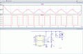
I am using similar circuit to the attached one
555 unnamed.gif

The design shows two 555, the one on the right side working as monostable and which is the one of my interested in this post.

The 10uF capacitor between pin 8-12 (threshold-trigger) and GND makes the monostable circuit to start ON when powering the circuit.

If instead of connecting the capacitor to GND I connected it to VCC makes the circuit to start OFF when powering the circuit, would this be a valid approach? Are there other ways to make the circuit to start OFF when powering it up?


Thanks
 

ericgibbs

Joined Jan 29, 2010
18,845
hi,
OK, so how do you control when the 555 Mono becomes triggered, is just at power On.?
A circuit diagram of your set up would be helpful, please post.
E
 

Thread Starter

Goxeman

Joined Feb 28, 2017
171
hi,
OK, so how do you control when the 555 Mono becomes triggered, is just at power On.?
A circuit diagram of your set up would be helpful, please post.
E
The circuit starts when power is ON. That is why VCC is connected to reset pin
 

ericgibbs

Joined Jan 29, 2010
18,845
Are there other ways to make the circuit to start OFF when powering it up?

Using the Reset pin with a Res/Cap circuit will hold Off the Mono, but you will have to use another method for triggering the the Mono.

A circuit diagram and purpose of your set up would be helpful, please post.
 

ericgibbs

Joined Jan 29, 2010
18,845
The circuit you posted, the right side is NOT a Mono it is an Astable.

What is the problem regarding posting your circuit??
 

Thread Starter

Goxeman

Joined Feb 28, 2017
171
The circuit you posted, the right side is NOT a Mono it is an Astable.

What is the problem regarding posting your circuit??
Whywoukd I redo a circuit that is already on the internet? My question was related to the 10uF connection to GND or VCC
 

ericgibbs

Joined Jan 29, 2010
18,845
Because you say that a Monostable action is required from the right side 555, it a free running Astable, not a Monostable.

You posted.
The 10uF capacitor between pin 8-12 (threshold-trigger) and GND makes the monostable circuit to start ON when powering the circuit.

I am trying to help you.

Update:
Your right side 555 in LTSpice.
 

Attachments

Thread Starter

Goxeman

Joined Feb 28, 2017
171
Because you say that a Monostable action is required from the right side 555, it a free running Astable, not a Monostable.

You posted.
The 10uF capacitor between pin 8-12 (threshold-trigger) and GND makes the monostable circuit to start ON when powering the circuit.

I am trying to help you.

Update:
Your right side 555 in LTSpice.
The circuit I’m trying to make is how you show. Thanks

That is a valid approach. Would you see any problem with it?
 

ericgibbs

Joined Jan 29, 2010
18,845
The problem is that whenever you apply the supply voltage the circuit will always run as an Astable, its Output, when High will enable the left side Astable.
The effect will be a bleeping sound in the speaker at approx 1 second intervals.

How would you like the circuit to operate.?
 

Thread Starter

Goxeman

Joined Feb 28, 2017
171
The problem is that whenever you apply the supply voltage the circuit will always run as an Astable, its Output, when High will enable the left side Astable.
The effect will be a bleeping sound in the speaker at approx 1 second intervals.

How would you like the circuit to operate.?
That is how I wanted it to work. In intervals, I will be modifying values manually to obtain the intervals I like better
 

Ramussons

Joined May 3, 2013
1,409
No problem. I am just curious to find out if I can do the same with other way around
No, You cannot.
Both the Threshold and Trigger points respond to a rising voltage which can happen only on a Charging Capacitor. If you connect the capacitor to Vcc, those voltages will remain at Zero indefinitely.
 

Ian0

Joined Aug 7, 2020
9,803
Yes, you can. If the cap is connected to Vcc then immediately After switch on, the circuit behaves as though the voltage has just exceeded THRESHOLD, and sets the output low. The capacitor is then charged negatively form the DISCHARGE pin until it reaches the TRIGGER voltage, from then it operates exactly the same as it would with the capacitor to ground.
But the right hand side is definitely an astable, not a monostable, (and the circuit should really be drawn with the operations moving from left to right for maximum clarity)
 

Thread Starter

Goxeman

Joined Feb 28, 2017
171
Thank you, I had some minutes to try and it works as expected when connecting the capacitor to VCC instead of GND
 

AnalogKid

Joined Aug 1, 2013
11,037
No, You cannot.
Both the Threshold and Trigger points respond to a rising voltage which can happen only on a Charging Capacitor. If you connect the capacitor to Vcc, those voltages will remain at Zero indefinitely.
Incorrect. The Trigger input "responds" to a negative-going input. Actually, it is level-sensitive, not edge-triggered. Whenever it is low (defined as Vcc / 3), it holds the internal flipflop in the state that drives the output high.

With the cap connected to Vcc and discharged when power is applied, the threshold voltage will be above (Vcc x .67), causing the Discharge output transistor to go low. This connects the timing end of the cap to GND (effectively), the cap starts charging, the Trigger/Threshold voltage decreases as the capacitor charges up until the voltage across the cap is (Vcc x .67), making the Threshold/Trigger input voltage (Vcc x .33). At this time the Trigger input sets the internal flipflop and the 2nd half-cycle starts.

And think about it. In the astable configuration, the timing capacitor is both charging and discharging in every cycle of the output. As long as the capacitor polarity is observed, the "other end" of it can be connected to any DC voltage between Vcc and GND. If that DC voltage is between (Vcc x .33) and (Vcc x .67) then the start-up condition might be ambiguous, but whatever it is the circuit *will* start oscillating. The first half-cycle will be shorter than calculated, but after that it will be a normal 555 astable.

AND - not only will the TS idea work, but it is an aspect of 555 operation that many people miss.

ak
 
Last edited:

ericgibbs

Joined Jan 29, 2010
18,845
AND - not only will the TS idea work, but it is an aspect of 555 operation that many people miss.
hi AK,
True, but the TS believes by connecting the Cap to Vcc, rather than 0v, the Astable will not run when power up.
E
 
Top