Stage Line 500W amp repair, help please

Thread Starter

Rookieme

Joined Jan 26, 2021
308
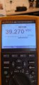
Wonder if i have some dry joints around IC3, its only since i have been probing around that area the thermal L Has came on and the protect light is on now 20210917_191325.jpg
 

LesJones

Joined Jan 8, 2017
4,509
It should not be possible to have 39 volts across the fan. From the wattage rating of the fan it should consume about 142 mA. That would mean that there would be 14.2 volts each dropped by R123 and R131. as we have 48 volts between +24 and -24 volt rails the fan should have a maximum of 48 - 28.4 - 19.6 volts across it.
Measure the voltage between collector and emitter of Q50, the voltages across R123 and R131. As something has changed (As the overtemp light is now on.) repeat the voltage measurements that you took in post #375 on the cathodes of D39 and D40.
Edit Are either LED 3 or LED 4 lit ? (overtemp indicators for each channel.) are the heatsinks hot ?
Les.
 
Last edited:
Measuring ripple:

You set the scope to AC coupling. The ripple will likely be <100mV p-p at a frequency of 2x he line frequency - e.g. 100 Hz. The +-15V supplies being OK, probably means ripple is OK.

==

You now have a fault. You can inspect/wiggle parts on the bad side and see if you get lucky or start actively troubleshooting.

You ave a good side to compare to.

D39 cathode = 14.78vdc
D40 cathode = --13.69vdc
Those measurements suggest a problem with the signs being different.
 

LesJones

Joined Jan 8, 2017
4,509
The readings in post #387 indicate the fault is related to the right hand channel.
What are the voltages on T14 and T16 with respect to T26 ?

Les.
 

Thread Starter

Rookieme

Joined Jan 26, 2021
308
I think i knew early on i was going to have a problem when i got here,
thats why i said i was concerened about the fan speed,
when i started this project the fan never spun up at all when i turned it on,
then something changed and it started working, when it did i noticed but had no idea why, And never chased the cause of this
 

LesJones

Joined Jan 8, 2017
4,509
Assuming things have not changed since post #385 and post #387. Then confirm that LED 3 (Thermal (l) is on and the voltage readings are
D39 cathode = 14.78vdc
D40 cathode = --13.69vdc
then measure the voltages on T13, T14, T15 and T16 with respect to T26.
Even if the conditions are not the same still report the readings and the state of LED 3 and 4
 

Thread Starter

Rookieme

Joined Jan 26, 2021
308
LED 3 L is still on, so is the overheat and protect LED on the front panel, right chanel still works and produces good audio
D30 cathode = 14.24vdc
D40 cathode = --12.58vdc
T13 = 0.508 vdc
T14 = 0.482 vdc
T15 = 0.433 vdc
T16 = 14.754 vdc
 
I suspect you may have swapped the T15 and T16 values.

Guessing Q42 or Q16 is open or bad connection. Take a look at the B-E voltage readings of Q42 and Q16.
==
Suggest paralleling (in the same direction as the B-E junction) a diode between

the base of Q42 and ground(E) and
the base of Q16 and ground(E)

temporarily one at a time and see if the LED goes out. The appropriate side of R151 or r152 is more appropriate to use. There will be a time constant.

The R152 voltages suggest something wrong with Q42, but it doesnlt make sense with the Left channel over temp light being on. e.g. open.

There could be a schematic error.

Guessing Q42 or Q16 is open or bad connection. Take a look at the B-E voltage readings of Q42 and Q16. Use a voltmeter while the amp is on, not the transistor checker.
 
Last edited:
Fan comments: Back in the 1980s fan replacements were common in mininicomputers and part of the PM. They are impedance protected and thus can sustain an indefinite stall. The culprit was always dust. One particular brand could be disassembled and cleaned.

I never saw any bearing wear.

The fan should rotate effortlessly.
 

Thread Starter

Rookieme

Joined Jan 26, 2021
308
Re done the test in post #394,
There are no breaks between Q42B and R152,
R152 bottom = 14.730 vdc
R152 top = 14.729 vdc
Q42 B= 14.730
Q42 E = 0.000
 

Thread Starter

Rookieme

Joined Jan 26, 2021
308
I suspect you may have swapped the T15 and T16 values
I did not get T15 and T16 mixed up


Guessing Q42 or Q16 is open or bad connection. Take a look at the B-E voltage readings of Q42 and Q16.
==
Q42 B and E voltage = 14.750vdc
Q16 B and E voltage = 0.433 vdc

Suggest paralleling (in the same direction as the B-E junction) a diode between

the base of Q42 and ground(E) and
the base of Q16 and ground(E)

temporarily one at a time and see if the LED goes out. The appropriate side of R151 or r152 is more appropriate to use. There will be a time constant
Tried this but there was no change and the left temp LED stayed on

Also please remember Q7 bias regulator on the left chanel is NOT CURRENTLY FITTED !!
 
Top