push-pull stage with MOSFETs

Thread Starter

ElectronicNewbie0

Joined Oct 18, 2025
54
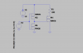
Hello, after researching i found out that its actually better making push-pull stages with MOSFETs

In this configuration i put both of the drain in common, and i changed the input ( square wave ) to 0-12.

Do u guys think this design Is fine? i will be able to drive the gate of the MOSFET at 1A? ( I didnt put any series resistor should i put one (?) )

In case how i should change my circuit?

The components i chose are : IRLZ44N and IRF9530 for the totem pair
While the MOSFET that will be driven is: IXTH360N055T2
 

Attachments

Ian0

Joined Aug 7, 2020
13,097
No - that won't work.
1. You have M1 and M2 back to front. If you want a non-inverting stage, then the drains go to the supply and the sources go to the output. As you have drawn it, you have the two body diodes in series shorting out the power supply.
If you want an inverting stage, then both devices have their sources connected to the supplies, and the output is on the drains, but the P-channel goes to the positive supply and the N-channel to the negative.

2. If wired as a non-inverting stage, it is a source follower, so the output voltage will only vary from about 3V to 9V. IRLZ44 is a logic-level MOSFET, it will be on with 2V on the gate. It will never turn off.
 

Thread Starter

ElectronicNewbie0

Joined Oct 18, 2025
54
No - that won't work.
1. You have M1 and M2 back to front. If you want a non-inverting stage, then the drains go to the supply and the sources go to the output. As you have drawn it, you have the two body diodes in series shorting out the power supply.
If you want an inverting stage, then both devices have their sources connected to the supplies, and the output is on the drains, but the P-channel goes to the positive supply and the N-channel to the negative.

2. If wired as a non-inverting stage, it is a source follower, so the output voltage will only vary from about 3V to 9V. IRLZ44 is a logic-level MOSFET, it will be on with 2V on the gate. It will never turn off.
Yeah i gotta switch the MOSFET P with the N
 

Thread Starter

ElectronicNewbie0

Joined Oct 18, 2025
54
What amount of current were you expecting at the gate?

And it's best to use real models for the MOSFETs as the default generic can have odd characteristics.
What amount of current were you expecting at the gate?

And it's best to use real models for the MOSFETs as the default generic can have odd characteristics.
Well i wanted to have atleast 1A, in order to approximate It i used ohm law, so I= Vout/Rout+R series, so i= 12V/1.2Ohm = 9A or around that value.

The average current i calculated It in a different way:
Iavg=QG•fsw , where QG Is 330nC and fsw= 10KHz

Iavg=330•(10-⁹)•10•10³=3.3mA


I try putting real models? But where can i find like a book or so explaining how do find expected current
 

Thread Starter

ElectronicNewbie0

Joined Oct 18, 2025
54
So how you you measuring the gate current?
That current occurs as a very short spike to charge the gate capacitance.
I tried measuring the current on LTSpice, but now im trying to import real models and see if the expected current Is as i calculated or not, lets see what i find out
 
Top