Stage Line 500W amp repair, help please

LesJones

Joined Jan 8, 2017
4,509
Q42 is faulty. (Base emitter open circuit.) Replace it. You could test the old one in your component tester. Note fixing this fault will not clear the fault with LED 3 being lit. It might even cause LED 4 to come on.
Note. while looking at this part of the circuit I cant find any pull up resistors on the signals control-L and control-R.

Les.
 

bertus

Joined Apr 5, 2008
22,964
Hello,

Is that the replacement of the 2SD1763?
Did the origenal have a metal tab?
If so the tab is also the middle pin connection.

Bertus
 

LesJones

Joined Jan 8, 2017
4,509
Re post #400. R152 and Q42 are only there to deal with over temp of the RIGHT HAND channel so they will have no effect on the left hand channel LED. With the base emitter junction in parallel with a diode (Connected with the correct polarity.) or the BE junction of another silicon NPN transistor what was the voltage readings in each end of R152 and the base and emitter of Q42 ?

Les.
 

bertus

Joined Apr 5, 2008
22,964
Hello,

Then you have now an isolated version, so the middle pin is not connected.
You could put a wire under the screw and connect it to the middle pin and see what happens.

Bertus
 

Thread Starter

Rookieme

Joined Jan 26, 2021
308
Re post #400. R152 and Q42 are only there to deal with over temp of the RIGHT HAND channel so they will have no effect on the left hand channel LED. With the base emitter junction in parallel with a diode (Connected with the correct polarity.) or the BE junction of another silicon NPN transistor what was the voltage readings in each end of R152 and the base and emitter of Q42 ?

Les.
Can i soulder a 1n4148 across Q42 ? Although with the diode check it reads 0.6 one way and OL the other way
 

Thread Starter

Rookieme

Joined Jan 26, 2021
308
Re post #400. R152 and Q42 are only there to deal with over temp of the RIGHT HAND channel so they will have no effect on the left hand channel LED. With the base emitter junction in parallel with a diode (Connected with the correct polarity.) or the BE junction of another silicon NPN transistor what was the voltage readings in each end of R152 and the base and emitter of Q42 ?

Les.
R152 now reads
Bottom end = 0.564 vdc
Top end = 0.614 vdc
Q42 B to E = 0.654 vdc

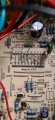
Solderings a bit rough, didnt use flux
20210920_213940.jpg
 

LesJones

Joined Jan 8, 2017
4,509
I did not realise until Bertus mentioned it the Q42 was a TO220 device.
Is Q42 the original device from before the fault occurred ?
If it has been replaced is it the original part number or has an alternative device been fitted ?
The collector is show as not being connected in the schematic. Can you confirm this and also check that the collector (Middle pin.) is NOT making electrical contact with the heatsink.
You can Connect a 1N4148 in parallel with the base emitter junction. (The cathode end of the diode to the emitter.) Measurethe voltage at the ends of R152 and the base and emitter of Q42 with the diode in place.

Les.
 

Thread Starter

Rookieme

Joined Jan 26, 2021
308
@LesJones
I did this in post #409,
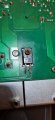
Yes Q42 collector is cut off, i am unsure if this hes ever been changed, however i do have another one with the same part numbers and the collector leg attached, i am sure this was one of the origanal outputs Q12, Q13, Q26, Q34 that i removed
20210920_204900.jpg

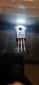
Here is the one i have spare
20210920_222812.jpg
 
What. Les said. Parallelling should make the fan stay on. You got voltages that make sense.

The temperature coefficient of the B-E voltage is -10mV/°C

Q42 open probably means not overtemperature.

Q42 shorted/shunted probably means overtemperature. The short can be through the heatsink.
 

LesJones

Joined Jan 8, 2017
4,509
Re post #410 I think I have asked you to measure the voltages at the cathode ends of D39 and D40. I don't think you have answered that question yet. That test will indicate which channel is indicating the fault and requesting high speed fan. The fact that LED 3 is lit indicates it is the left hand channel. I suggest fixing the fault that we have been tracing around Q42 before jumping to a different fault. I would remove Q42 and test it in you component tester. I have seen nothing to explain why at one point you had about 14 volts on the base of Q42 an at another time you had about 0.5 volts on it.

Les.
 

Thread Starter

Rookieme

Joined Jan 26, 2021
308
Re post #410 I think I have asked you to measure the voltages at the cathode ends of D39 and D40. I don't think you have answered that question yet
Post #393


I have seen nothing to explain why at one point you had about 14 volts on the base of Q42 an at another time you had about 0.5 volts on it.
I think i was testing in the wrong place, but i can do it again no problem
 
Can i soulder a 1n4148 across Q42 ? Although with the diode check it reads 0.6 one way and OL the other way
Odd.

If q42 is bolted to the heatsink, remove that connection

Before you do measure the voltage between b and e with your dmm with the power on.

Something isn't right. I thought you measured a voltage on r152 that goes to the base of q42 and got different numbers?
 
The pic in post 412 suggests that the right connection isn't solid. Try ohmmeter between the lead and the copper. Put the probe close to the body so you don't push down on the right lead so it makes contact
 

Thread Starter

Rookieme

Joined Jan 26, 2021
308
The pic in post 412 suggests that the right connection isn't solid. Try ohmmeter between the lead and the copper. Put the probe close to the body so you don't push down on the right lead so it makes contact
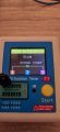
There was indeed a brake between Q42E and R152, tested Q42 in thr tester, see photo

I think this is good
20210921_191421.jpg
 
I'm reading it as it good there was a break and you found it.

Or I can read it as the transistor is good.

Both are valid. Next step. Did the thermal light go out?

What is the B-E voltage on the complement to Q42? Use your DVM with power on, not the tester.

The B-E voltages are being used as an uncalibrated temperature sensor. Every deg C, the voltage across the B-E junction drops -10 mV.

calibrated versions are used in cryogenics: https://www.omega.com/en-us/sensors-and-sensing-equipment/temperature/sensors/rtd-sensors/p/CY670
 
Top