Stage Line 500W amp repair, help please

A few comments after reading both websites:
1. No load testing is more important than load testing of the amplifier.
2. Q29 in the long run should use some sort of thermal conductive adhesive not grease.
3. There is consumer audio levels and pro audio line levels. https://en.wikipedia.org/wiki/Line_level
4. Audio capacitors. Usually those in the signal path are metalized polyester. 1-10uF is sometimes electrolytic because of the cheaper cost. Different caps might be used in a phono pre-amplifier equalization.
5. A note about polarization. It's not well known, but even a non-polarized capacitor can be installed the wrong way. it's primarily a valve/tube phenomenon. Those vintage capacitors have the outer foil marked with a polarity symbol of sorts. e.g. a band. It's important that the outer foil goto the lower impedance side of the circuit. Detecting which side is the outer foil side is another topic.
6. I'd be interested in knowing what the slew rate of the amplifier is? This is the time from 10% to 90% voltage with a square wave input.
7. Horn speakers driven by tube amplifiers seem louder (it makes sense)
8. There is a lot to be learned in this http://leachlegacy.ece.gatech.edu/lowtim/ artical/
I built an amp based on that design.

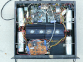
The amp I built: The case was made from scratch and is 2RU (Rack Units) high. A custom 4x35VAC torroidal transformer. Exponential turn-on audio ramp; slow turn-on. Amps can easily be removed for troubleshooting.
1631396267213.png


1631396267213.png
 

Thread Starter

Rookieme

Joined Jan 26, 2021
308
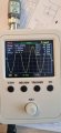
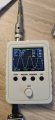
I dont think i have any 2.2Ω resistors, i tried 6 10Ω 3 in parallel either side to get just over 6Ω and it didnt take long to meke them smoke, i only managed to get about 3 quarters volume on the amp, i flicked the scope over to single to hold / record the readout, the scope was still on x1 input20210912_184011.jpg20210912_184002.jpg
 

Thread Starter

Rookieme

Joined Jan 26, 2021
308
The 630ma fuses i ordered came yesterday to replace F7 and F8, i fitted them into the amplifier only to see them blow as soon as i switched the amp on, the original ones i removed looked like a material strand with fuse wire wraped around it, the new ones were just wire, were the originals slow blow or a different kind ?, i currentley have standard 1A-250v in place, this is the lowest rating that didnt pop as soon as it was switched on
 

Thread Starter

Rookieme

Joined Jan 26, 2021
308
If the resistance between Q34E and Q36B is really 0.85 ohms then there is a high resistance connection between those points.
I suspect there are srands of wire broken in your test lead which are causing varying reading. (This will probably be where the wire flexes most near the ends.) Test the resistance of the leads before and after doing the measurements and assuming the readings are the same subtract that value from the displayed reading. If you can't get consistent reading make up a set of new test leads.

Les.
I will do this tomorrow and post my results with my spair test leads
 

Thread Starter

Rookieme

Joined Jan 26, 2021
308
I fear i may have binned the origanal fuses,
Why is this information not on the schematic?

Is this part of the soft start, or are they just slow blow to cope with the initial inrush of current untill everytng settles down ?
 
Last edited:
Well, a property of an inductor is that "the current can't change instantaneously" which essentially means that the circuit sees the winding resistance the moment it's turned on.

The corollary for capacitors is that "The voltage across the capacitor cannot change instantaneously" The system sees, the ESR (Effective Series Resistance) when voltage is first applied.

cope with the initial inrush of current untill everytng settles down
This is the usual reason.

You don't have a service manual and you don't have a parts list. Many service manuals just had the OEM's part number. Fuses are usually better specified.

But, https://www.fluke.com/en-us/products/accessories/fuses

has no information, because they want you to buy them from Fluke.
 

Thread Starter

Rookieme

Joined Jan 26, 2021
308
@LesJones in post #322 i was not able to turn the volume up to full, the resisters i had could not take it and started to burn RAPIDLY, i did notice on the scope that the + side seems a bit lower than the -- now
 

LesJones

Joined Jan 8, 2017
4,509
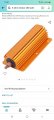
I don't understand why you even tried to use these resistors for a dummy load that would cope with 125 watts. (That is the rated output per channel for the amplifier.) You need to build an 8 ohm dummy load capable of dissipating at least 125 watts.
You don't have to have the volume control set to maximum. The position required to give the rated output depends on the input signal level.

Les.
 

Thread Starter

Rookieme

Joined Jan 26, 2021
308
With new test leads i measured the resistance between Q34 Emitter and Q36 Base, minus the resistance of the test leads i get 0.02Ω, leads alone read 0.14Ω and the connections betweer transistors 0.16Ω
 

LesJones

Joined Jan 8, 2017
4,509
That looks ideal but it is probably very expensive. You will also need a large heat sink to mount it on.
I normally manage to make something up from my stock of wire wound resistors and old heating elements.
There are some reasonably priced 100 watt heat sink resistors on ebay but you would have to wait for them to arrive from China. You should not try to run the amplifier for long at 100 watts sine wave output. With music (Which is what it was designed for the average power would be much less when the peak level was 100 watts.)
Your resistance readings are are OK so that's one less thing to worry about.

Les
 
Last edited:

Thread Starter

Rookieme

Joined Jan 26, 2021
308
Thats partly my issue, i dont have many spare parts, just what i have bought to try repair this amp, however i do work for a UPS (uninteruptable power supply) Company who manufacture there own chargers so sure i could find something lying around in the kit we remove to be binned ,
Also buying diodes and resisters is a bit of a pain now as my local Maplins has closed and i have to order everything online, i already know D4 on the left chanel is dead as i was compairing channels a while back and that reads dead short annode to cathode and the same in reverse, will remove and test tho when we get to that stage
 

Thread Starter

Rookieme

Joined Jan 26, 2021
308
Found an old 6 Ω speaker to try test the max output, set my scope to x10 and this is the reading just before it started to clip, (sine wave goes flat at the peaks ) not gonna lie deafening at 500Htz 20210913_185116.jpg20210913_185019.jpg
 

LesJones

Joined Jan 8, 2017
4,509
I think there is something wrong with the readings. The scope is showing almost -80 volts for the negative peak. The supply rails to the output are marked + 45 and -45 volts. I would not be surprised if they were a bit higher or lower than these values. It is not possible for the output to get outside those limits. WITHOUT changing any settings touch the scope probe tip on each rail in turn (T6 and T8). Report what the scope displays for Vmax an Vmin. If you were not using the x10 probe in post #322 you may have damaged the input of the scope.
Also measure the voltage on T6 an T8 with respect to T9 using your meter.

Les.
 
Last edited:
Top