I think @Rookieme is doing a great job considering that he has limited electronics experience. But he sure will have a lot more of it when the amp is fixed. Keep it up, Rookieme!
Thats exactly what i am trying to do, but sometimes you dont explain yourself very well, the solder job in the photo is a quick fix untill everything is working then i will clean everything down and make a permant repair, the kit i have is not the best and the nib of the iron is a bit on the large side, my temp controled iron broke unfortunately so this is all i have untill payday comes around again,
I read the first part of the history of the amplifier. I think the problem started with an offset voltage on one channel. That could have damaged the speaker. When it was switched to bridge mode the offset on the output of one channel could have damaged the other channel. (I am assuming you understand what a bridged configuration is. If you don't then you could google it or I could explain it.) I has assumed that you realised we were checking the forward voltage drop on the base emitter junctions of the emitter follower stages. (You said in one post that you understood that the forward voltage drop across a silicon diode was about 0.6 to 0.7 volts.) The base emitter junction can be thought of in a similar way to a silicon diode. So for the test we were doing on the 4 emitter follower stages thought of a 4 silicon diodes in series to make it easier to understand. If you can understand that simplification then you can start to consider that the collector current of the transistors and the resistors in the circuit will effect the simplification of the diode analogy. If you look at the voltage readings on the positive half of the amplifier thet the voltage across each base emitter junction is not too far away from 0.6 volts. But on the negative half it APPEARS that the base emitter voltage on Q34 is about 0.85 volts. This may be Q34 is faulty or a broken track between between Q34 emitter and Q36 base. It is easier to do a resistance check between Q34 emitter and Q36 base than to remove Q34 to test it.
Maybe now you can see why I requested the voltage readings to be laid out the way I did.
I get that and understand, thank you, the resistance between Q34 emitter and Q34 base is 0.97Ω, the track looks good and joints are ok ,Q29 is not attached to the heatsynk never has been from the factory, it does sit close but thats it, i will find some way of securing it when its finished
Cleaned a couple of solder poins up again after Q40 base decided to detach, (cought the transister while removing the board, i need to shorten the legs) repeated the test AGAIN in post #294 and i think the results look reasonable
in post #304 you say " Q34 emitter and Q34 base is 0.97Ω, " Is that the test you did or is there a typing error ? (Is the 0.97Ω, reading what was displayed on the meter or corrected for the resistance of your test leads ?)
The readings in post #306 seem OK. I don't understand what has changed as you have not repaired a track or replaced Q34.
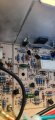
All i did was remove the board to check the etch between Q34 emitter and Q36 base, in doing that i snagged Q40 on a wire and broke the base leg connection, (noticed this after refitting the board and tested for audio) while i had the board out i went over Q34 solder points, as you rightly pointed out they were terrible, then refitted the board, tested i had clear audio again and repeated the test,
And yes sorry i meant Q34E and Q36B
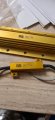
I suggest that you test the amplifier with the 10 ohm load with the same input signal level as before and check that the output is a clean sine wave. If that is OK then you will need a high power (150 watts or greater.) 8 ohm resistor as a dummy load so that you can test it up to full power. (You will also have to re fit the fuses on the 45 volts rails to run it at full power.)
So here is a question, i owned this amplifier before it was broken and depending on what kind of input you put in, (i used to use a mixer with preamp) depends on the max output,(volume) how am i going to judge this ?
And am i supposed to be getting feedback/ resistance to the fuses, this is at 500htz in, and the volume on 2, output resistors connected, or is the just the limitations of the resistor fuses ?
You will see an AC voltage across the resistors that are in place of the fuses as the amplifier will be drawing some current.
Shortly after you came back to this forum I suggested injecting a signal from the signal generator to an input on the amplifier to give a value of voltage at the input of the power amplifier of a particular voltage (I can't remember the value I suggested.) This was to confirm that the power amplifier was giving a voltage gain of about 6. (The ratio of the feedback resistors R67 and R79)
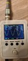
I assume this is about the signal level you have been using so far. To test at higher power levels just increase the output from the signal generator or increase the gain in the preamplifier section to give the desired output level. The maximum output will be a bit less than 90 volts peak to peak. (This is the level at which it will clip the peaks of the sine wave as the output cannot go outside the + and - 45 volt rails.) (This will be about 31 volts RMS) When increasing the drive level slowly monitor the output with your scope looking for any visible distortion of the sine wave at the output until you reach close to 90 volts peak to peak. (You will probably have to use a X10 scope probe to reduce the level at the scope input.).
Four of the 2.2 ohm resistors in series will give 8.8 ohms which should be close enough.
If you used the 150 ohm resistors you would need 18 of them in parallel. to give 8.33 ohms.
If the resistance between Q34E and Q36B is really 0.85 ohms then there is a high resistance connection between those points.
I suspect there are srands of wire broken in your test lead which are causing varying reading. (This will probably be where the wire flexes most near the ends.) Test the resistance of the leads before and after doing the measurements and assuming the readings are the same subtract that value from the displayed reading. If you can't get consistent reading make up a set of new test leads.

 Facebook
 Google
 GitHub
 Linkedin