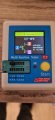
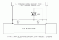
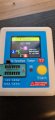
Here is the transistor i removed from Q29 in the tester,
also the voltage between the new Q29 collector and emitter is 4.00vdc , bang on what you expected les
This does not make sense. The bias regulator now seems to be working correctly but the suspect transistor that you removed looks to be OK in the tester. When you did the voltage tests in post #190 you got 1.36 volts between the emitter and collector of Q29.
With no signal input on no load resistor connected to the output measure the following voltages.
Q23 base to Q40 base. (I expect this to be 4.17 volts.)
With the black lead from your DMM connected to T9 measure the voltages at the following points and present the results laid out as below. Include the polarity of the readings
Q23 base Q40 base
Q25 base Q37 base
Q26 base Q34 base
Q28 base Q36 base
Q28 emitter Q36 emitter
T10
What value of resistors have you fitted in place of the fuses ?
Q 37 looks OK. Solder it back in the board and look for damage to the etch between Q37 collector and Q34 base and check the solder joint to Q34 base. That is all I can think of at the moment. I will have to try to think of another explanation.
Would it be possible to inject a signal into the r-in and bypass the pre amp, this could possibly show if the problem is further back in the circuit ?
Also do you think it could be the resister fuses limiting the current to the main amp ?
You just seem to be going away from the problem. We know the present fault we are chasing is very close to Q37. I cant see any logic in your ideas. Now you gave soldered Q37 back in measure the resistance between Q37 emitter and Q34 base. When we fix the problem with the negative side emitter followers the 39 ohm resistors in place of the fused may have to be reduced as we don't know the designed value of the quiescent current for the output stage.
Q37 has been re installed, also Q40 has been replased as the pad it was soldered to has detached from the board and the old one would not go back through the holes, with my meter on Ω setting and the negative probe on Q37 emitter and positive on Q40 base i get 431.30KΩ, if i reverse the leads the reading slowly climbs
Measuring the resistance between Q37 emitter and Q34 base was the test I requested. That was to try to identify why the seems to be a voltage drop of 3.465 volts between Q37 base and Q34 base when the transistor tester shows that the base emitter junction of Q37 is OK. It is the test between Q37 emitter and Q40 base that I don't understand.
I do t believe this amp!!,
I now have a new problem, turned it on tonight to complete the testing and the fan stopped and now i have no power lights on or anything, you can hear the transformers come on and hum, the + and --45v rails have power but the main board is dead, all fuses look to be ok, i checked the plug at connection 10 and have 56vAC relative to earth (chassis)
Ok, sorted that , for some strange reason F8 and F9 630ma 250v decided to let go, i have just noticed that the amp will power up with eithe F8 or F9 in place , so its possible one of them had been blown for a long time, i will order some replacement and some for where the resistor fuses are for future

 Facebook
 Google
 GitHub
 Linkedin