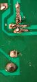
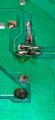
What do you think the resistance between Q37 emitter and Q34 base should be ? You should be able to answer this question by looking at the schematic. I am trying to get you to follow the reasoning for these tests.
Looking at the schematic Q37E is directly connected to Q34B so about 1 to 2 Ω, i said this as this is what i get connecting the probes together, so basically i am getting the resistance or the PCB track
Good. So are you going to try to trace the cause of this fault yourself ? If you want us to try to identify it you will have to post VERY CLEAR pictures of the etch side of the board close to Q37 and Q34. ( See post #268. )
I have a question !,
So as far as i can work out this works on a balance of + and -- input relative to the 0v rail, my queation is if i have repaired a section of the PCB track, say with covering the track with solder or use a pice of wire to connect one componant to the next because some of the tracks are bad, would this difference in resistance effect the current flow and would i have to do the same for the opposite rail for it to still be (balanced) and yes i can take good photos if needed,
It is unlikely to make any significant difference in the resistance of the track. Even if it is just a hairline break in the track solder a suitable thickness wire across the break,(Don't just rely on a blob of solder.) There will probably be solder resist on the track which you will have to scrape off to be able to solder to it.
Q 37 looks OK. Solder it back in the board and look for damage to the etch between Q37 collector and Q34 base and check the solder joint to Q34 base. That is all I can think of at the moment. I will have to try to think of another explanation
Just find the break in the track between Q37 emitter and Q34 base and repair it. The chance of having the same fault on the left hand channel is VERY small. You seem to be going off at a tangent again wanting to do tests that have no relevance to the fault.
Hats off to you @LesJones , there is indeed a brake in the track where Q34 base connects to the etch, its connected on one side but not the emitter side of Q37,
Ok repaired that,
NOW!!! WE HAVE ONE SIDE WORKING, and sounds nice and clear, still have the resister fuses installed,
Whats my next steps?
Even though it seems to be working I suggest taking the voltage readings again and layout the results as I showed them in post#266. Now the transistors on the negative side are conducting it will change the readings on the positive. Post the results and also make a note of them as it may be useful when fault finding the left hand channel. Before you try the amplifier at higher output levels MAKE SURE that Q27 is in good thermal contact with the heat sink with the output transistors. (As I have not seen the amplifier I don't know how Q27 is secured to the heat sink.) If this is not done it is likely that the output stages will go into thermal runaway which could destroy the output transistors.
Q27 is not fitted along with the corresponding Q35, i am assuming you meant Q34, this is held to the heatsynk with a metal spring like clip ( not currently installed), once you are happy everything is good i will dismantle, clean and thermal paste everything,
When I said Q27 I should have said Q29 (The bias regulator) Sorry for the error.
Something is still not right around Q34 and Q36. Check the resistance between Q34 emitter and Q36 base.
On the side that works, you should look at the voltage across any of the last emitter resistors over time with no load and no signal. At least an hour.
Hi kiss, I have no idea of the history of the amplifier so I had no hints at the sorts of faults it was likely to have. I did ask for the history of the amplifier but the question was not answered. Looking at the pictures of the etch side in post #289 it looks like someone that had never soldered before has had a go at it. I feel that Rookieme is just following instructions but not attempting to understand the reasoning behind the tests.

 Facebook
 Google
 GitHub
 Linkedin