 Facebook
 Google
 GitHub
 Linkedin
Hi,
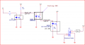
For my requirement I'm using phoenix contact SSR 2966595 (24DC/2A) which fails frequently after 15-20 days of usage.Which is operating at 10hz. The SSR input connected to opto isolator & output connected to input of 001 KDD 06100 (4-32VDC/10A) SSR relay. please help me is am doing anything wrong.In below schematic need to be improve?
below is the schematic which give clear picture.
SSR1 2966595 have input internal resistance 3.1K, & SSR 2 have input internal resistance of 2.1K.

Thanks,
For my requirement I'm using phoenix contact SSR 2966595 (24DC/2A) which fails frequently after 15-20 days of usage.Which is operating at 10hz. The SSR input connected to opto isolator & output connected to input of 001 KDD 06100 (4-32VDC/10A) SSR relay. please help me is am doing anything wrong.In below schematic need to be improve?
below is the schematic which give clear picture.
SSR1 2966595 have input internal resistance 3.1K, & SSR 2 have input internal resistance of 2.1K.
Thanks,
Attachments
-
 16.4 KB Views: 10
 -
 16.4 KB Views: 10


