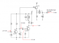
Another though as you mentioned previously it could be a defective relay, meaning the contacts are shorted together or have been bypassed with a jumper or sorts on the PC board.
Thank you very much bro, you are a star!! this will be very helpful for my investigation! I will check those component and I will let you know how is going..I have checked some of those component before on the begin of this repair but obviously I 'm missing something here, I remember also that I have checked C8.Anyway with your clarification on how this thing work, I should be able to find the problem and hopefully solve it (hopefully) again, thank for your time, I will update soon Ciao
I was thinking that I don't hear the click not even as soon as I turn it on, because of this I'm was still wondering if the relay could be stuck close, I don hear it with no speaker connect to it, so no click at all.. Could it be a possible?
You already answer this question, you read my mind I will check what you suggested and than if can find anything I will try a new relay
There are a couple of test you can perform to see if the relay circuit is functioning correctly.
Back in post #65 you mentioned you could here the relay click when powered OFF is that still happening?
There are a couple of test you can perform to see if the relay circuit is functioning correctly.
Back in post #65 you mentioned you could here the relay click when powered OFF is that still happening?
Good morning! No unfortunately I don't hear it anymore (i'm suspecting that I was hearing the click of the power supply relay) I was thinking of touch the + & - with 6v battery to see if it move/click! But I will wait for you suggestion before doing anything....
Good morning! No unfortunately I don't hear it anymore (i'm suspecting that I was hearing the click of the power supply relay) I was thinking of touch the + & - with 6v battery to see if it move/click! But I will wait for you suggestion before doing anything....
I have checked C8 I did replace it as well, but nothing! Also I check Q2 and seams to be ok! sorry for wrong information Yes I hear it clicking on off but not on power on, the music come out with no delay, do you want me to check also R7? I will check the voltage as well, but need time as I have to go out...
Try and verify the voltage across C8. It should increase from 0 to maybe 6 volts in about 2 seconds when first powered ON. If that is happening then C8 and R7 are OK. Now try this, after the unit is powered ON short out C8 with a jumper or low value resistor (under 1K). If Q2 is good the relay should drop out and you should hear the click.
Hi, thank you so much bro! I will try all the above as soon as I can, and i'll let you know (I'm not in London, will be back tomorrow evening) As always your help is much appreciate!
Hi, thank you so much bro! I will try all the above as soon as I can, and i'll let you know (I'm not in London, will be back tomorrow evening) As always your help is much appreciate!
Try and verify the voltage across C8. It should increase from 0 to maybe 6 volts in about 2 seconds when first powered ON. If that is happening then C8 and R7 are OK. Now try this, after the unit is powered ON short out C8 with a jumper or low value resistor (under 1K). If Q2 is good the relay should drop out and you should hear the click.
Hi , bro, I'm in trouble now, I checked the TDA on pin 10 as suggested, but mystically I touch one pin, 10 with pin 8 or pin 10 with pin 12 ,not sure, consequently, R2 blow up, I did replace R2 but it blow again what happen this is a nightmare! It was working perfectly the guy wont the click, now?...I'm working on it but I'm so frustrate.....
Sorry to hear that.
If R2 was smoked I would suspect Q10 and all associated components with that -12 volt supply. Need to check all power supply voltages.
Sorry to hear that.
If R2 was smoked I would suspect Q10 and all associated components with that -12 volt supply. Need to check all power supply voltages.
[/QUOTE
thank you bro, I checked Q10 right now and it look like ok to me, honestly i don't know where to start, could I have damage the TDA? Last time it keeping blowing the R2 and it stop only after changing TDA, could be the TDA? I'm sure I short pin 10 with some other pins by checking it, that's why I do suspect it. Let me know what do you think
Is that a known good TDA chip you installed. I don't see how the TDA would have anything to do with R2.
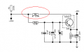
Are we talking about this R2 in the red circle?
There are checks you can do with the meter without turning on the amp.
Is that a known good TDA chip you installed. I don't see how the TDA would have anything to do with R2.
Are we talking about this R2 in the red circle?
There are checks you can do with the meter without turning on the amp. View attachment 268950
The above schematic doesn't make sense to me. The TIP137 is a PNP yet there is a direct connection from the emitter to -12V. Am I missing something here?
The above schematic doesn't make sense to me. The TIP137 is a PNP yet there is a direct connection from the emitter to -12V. Am I missing something here?
Hi, you should have the same schematic, did you fix yours? I did and it was working perfectly but the guy (the owner) wanted the click back, but unfortunately he get a bang instead I was investigate the click thing, but as I say something went wrong by checking the TDA, now i'm again at starting point..I check a lot of component but I can't find what cause this R2 to burn! Could you please help?
The above schematic doesn't make sense to me. The TIP137 is a PNP yet there is a direct connection from the emitter to -12V. Am I missing something here?
I meant that they looking in work condition, I misure Q10 by touching with the red lead to the base, the black to the emitter, than by keeping the red to the base I touched the collector no current flow in both directions, it does on the other side. The C31 with an option to insert it, which is on my multimeter, which was less than 4,7 it was 3.8 if I remember well the D3 has been replace...

 Facebook
 Google
 GitHub
 Linkedin

 I will check what you suggested and than if can find anything I will try a new relay