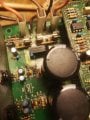
As you can see the track has burned and i did a bridge just to try it now! Normally I do the bridge under the board! Also the diode track is burned but it's connected 100% It's look a mess but is not has I intend it is as it is just to try now
no, as the track is broken and I bridge it, didn't make sense to me to do it nicely as it keeping burning the R2, when it will work I will connect R2 to the collector from under the board
OK. One final check, measure the resistance from ground on all three legs of Q10 again using the 20K scale.
You did remove the 10 ohm resistor correct?
OK. One final check, measure the resistance from ground on all three legs of Q10 again using the 20K scale.
You did remove the 10 ohm resistor correct?
base 8.50 but is going up very slowly it will stop, collector 13.00 still was going up fast. emitter 1.45. Do you mean the R2? yes I put the 2 of 505 to make 1k
base 8.50 but is going up very slowly it will stop, collector 13.00 still was going up fast. emitter 1.45. Do you mean the R2? yes I put the 2 of 505 to make 1k
brother i'm very sorry but in London is almost 1.30am, tomorrow I have to get up early, do you mind if you continue tomorrow late morning 10-11? I would like to see if works but I can't stay anymore. Thank you very much for your precious help, speak tomorrow (if you can of corse) Ciao
Sure I was having dinner so sorry for the late reply. I'm in Colorado, do you mean 10 am your time or mine because it's 6:56 my time as I post this. I think you are about 6 or 7 hours ahead.
Sure I was having dinner so sorry for the late reply. I'm in Colorado, do you mean 10 am your time or mine because it's 6:56 my time as I post this. I think you are about 6 or 7 hours ahead.
Hi bro, I meant in my time, but I didn't consider that in there is night time, when is best for you tho, sorry but I seen your message only now....I haven't start it yet, I was thinking that the source of my problem has been me shorting pin 10 with pin 12 or 8 (can't tell you for sure) of the TDA, but you said, that you don't see what the TDA have to do with R2, so I'm confuse, perhaps the reason for R2 to "explode" was different one? And as it happen when I was testing the TDA, perhaps it make me believe that the cause was me shorting something? Could it be? To test TDA, I have to do from the back of it, so the board was out, not attached to the heatsink! Anyway just wandering, because nothing make sanse to me....I will be surprise if it does work, It would make me even more confuse..But when you ready I'm ready
Maybe the schematic for the 150 Plus is slightly different then the 150 as far as the TDA chip is concerned. From the schematic you posted there is no physical connection between the TDA circuit and the minus 12 volt supply (Q10). Or another possibility the board has been modified on a previous repair.
Also on the TDA7294 pin 12 and pin 11 are NC which means no connection inside the chip. If you shorted pin 10 to pin 8 that could possibly damage the TDA based on what I see on the schematic. It doesn't make any sense to me either why R2 would explode but that schematic is all I have to go on.
Before we proceed you did remove the 10 ohm resistor R2 and replaced it with the 1K correct?
Maybe the schematic for the 150 Plus is slightly different then the 150 as far as the TDA chip is concerned. From the schematic you posted there is no physical connection between the TDA circuit and the minus 12 volt supply (Q10). Or another possibility the board has been modified on a previous repair.
Also on the TDA7294 pin 12 and pin 11 are NC which means no connection inside the chip. If you shorted pin 10 to pin 8 that could possibly damage the TDA based on what I see on the schematic. It doesn't make any sense to me either why R2 would explode but that schematic is all I have to go on.
Before we proceed you did remove the 10 ohm resistor R2 and replaced it with the 1K correct?
The schematic is for the one I got, I get it from factory and the guy confirm that this is the one for the plus..Yes could be that I shorted pin 10 with 8 but I replace TDA. Anyway, yes i did what you said, I did replace the 10 ohm with 1k

 Facebook
 Google
 GitHub
 Linkedin