Square wave 0-10volts to -5 +5 volts

Thread Starter

Tony Elliott

Joined May 8, 2015
160
Hi All,

I need to make a square wave generator that outputs a squarewave 0-10 volts compatible with my eurorack modular synthesiser -5 +5 volts, any suggestions very welcome.
 

#12

Joined Nov 30, 2010
18,224
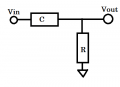
Capacitive couple into a resistor to ground will move the center of the wave to zero volts.
Output connection is the junction of the capacitor and the resistor.
 

Thread Starter

Tony Elliott

Joined May 8, 2015
160
Capacitive couple into a resistor to ground will move the center of the wave to zero volts.
Output connection is the junction of the capacitor and the resistor.
This sound like a very nice simple solution, Is it possible to send a quick sketch please, as I am finding it a little tricky to visualise.
 

WBahn

Joined Mar 31, 2012
32,973
Here's the topology he's suggesting:

RCHPF.png
What frequency is your squarewave? Does the frequency change at all?

This is a high pass filter, so the RC time constant (the product of the resistance and the capacitance) has to be chosen correctly.

In order to preserve the square wave nature but remove the DC component, you need the time constant to be well above (i.e., longer than) period of the fundamental frequency of your square wave.

Also, if your square wave turns on or turns off there will be a period of distortion while the waveform stabilizes.
 
Last edited:

Robin Mitchell

Joined Oct 25, 2009
819
I would suggest a different approach for a synthesizer. If you have a split rail supply available then just pass the signal through a differential amplifier with a gain of 1. For the -V input supply 5V. The V+ has your square wave and the differential amplifier will subtract 5V resulting in +-5V
 

crutschow

Joined Mar 14, 2008
38,578
................
In order to preserve the square wave nature but remove the DC component, you need the time constant to be well below the fundamental frequency of your square wave. .................
To perhaps clarify, that means the time constant be large enough so the the the HP filter corner point is well below the fundamental (at least a factor of a 100 below for small droop of the square-wave).
 

WBahn

Joined Mar 31, 2012
32,973
Probably -- I haven't look at it in detail, but there are many similar circuits that can do what you want. There are difference amplifiers and summing amplifiers. That amplifier appears to be an inverting amplifier, so the waveforms they show in the figure for the output are misleading because the will be inverted relative to what's shown. But if that's an issue, you can always add a second amplifier to reinvert the signal.
 

WBahn

Joined Mar 31, 2012
32,973
To perhaps clarify, that means the time constant be large enough so the the the HP filter corner point is well below the fundamental (at least a factor of a 100 below for small droop of the square-wave).
Yeah, I realized that my wording wasn't very good so I updated it. I don't know if the TS knows about time constants and their relationship to cutoff frequencies or even how frequencies relate to a square wave, so I figure we may need to fill in some gaps as we get a better feel for the TS's state of knowledge.
 

Thread Starter

Tony Elliott

Joined May 8, 2015
160
Probably -- I haven't look at it in detail, but there are many similar circuits that can do what you want. There are difference amplifiers and summing amplifiers. That amplifier appears to be an inverting amplifier, so the waveforms they show in the figure for the output are misleading because the will be inverted relative to what's shown. But if that's an issue, you can always add a second amplifier to reinvert the signal.
Il try and add an extra amplifier tomorrow to re invert the signal.
 

Tonyr1084

Joined Sep 24, 2015
9,744
If I read your question right you have a ±5V square wave and you want to output a 10V square wave with logic 0 at ground and logic 1 at 10V. Is that right? If so then all you need is a buffer (or buffer/inverter if phase is of no consequence). Let your +5 be your logic level 1 and let your -5 be your logic level 0. You shouldn't get any current out of the buffer input so the negative voltage should be of no consequence.
 

WBahn

Joined Mar 31, 2012
32,973
If I read your question right you have a ±5V square wave and you want to output a 10V square wave with logic 0 at ground and logic 1 at 10V. Is that right? If so then all you need is a buffer (or buffer/inverter if phase is of no consequence). Let your +5 be your logic level 1 and let your -5 be your logic level 0. You shouldn't get any current out of the buffer input so the negative voltage should be of no consequence.
I think it's the other way around. The signal he is starting with is the output of some kind of signal generator and it is 0 V to 10 V and he want to produce a signal that if -5 V to +5V.

@Tony Elliott : What kind of signal generator are you using to get the original 0 V to 10 V squarewave? Does it have any kind of offset adjustment?
 

Thread Starter

Tony Elliott

Joined May 8, 2015
160
I think it's the other way around. The signal he is starting with is the output of some kind of signal generator and it is 0 V to 10 V and he want to produce a signal that if -5 V to +5V.

@Tony Elliott : What kind of signal generator are you using to get the original 0 V to 10 V squarewave? Does it have any kind of offset adjustment?
It's a very simple squarewave generator 555 timer 4013 flip flop IC's. With a very large frequent range. I have added a toggle switch with different value capacitors to use a range I frequencies with a paint resistor. It has no off set adjustment.
 

WBahn

Joined Mar 31, 2012
32,973
It's a very simple squarewave generator 555 timer 4013 flip flop IC's. With a very large frequent range. I have added a toggle switch with different value capacitors to use a range I frequencies with a paint resistor. It has no off set adjustment.
What voltage supplies are available to you?

What is the minimum and maximum frequency of your square wave that needs to work?
 

Thread Starter

Tony Elliott

Joined May 8, 2015
160
What voltage supplies are available to you?

What is the minimum and maximum frequency of your square wave that needs to work?
I have a bench power supply so I have a large range of power supply.
The frequency range is high to LFO so a very large range. The oscillator is powered by a 12v battery.
 

WBahn

Joined Mar 31, 2012
32,973
I have a bench power supply so I have a large range of power supply.
The frequency range is high to LFO so a very large range. The oscillator is powered by a 12v battery.
So you are using a 12 V battery for the square wave generator circuit? And you are using the bench supply for the voltage translation circuit? How are you connecting the circuits to establish a common ground? Is the bench supply bipolar?

Are you planning on using the battery and the bench supply for this system after you have finished developing it?

I have no idea what you mean by "high to LFO". How about some values? You lowest frequency square wave of interest is how many Hz? You highest frequency square wave of interest is how many Hz?
 

AnalogKid

Joined Aug 1, 2013
12,182
The frequency range is high to LFO so a very large range.
Actual numbers...? To repeat post #17:
"What is the minimum and maximum frequency of your square wave that needs to work?"

Also, with a single power supply you cannot get an output signal that extends down to -5 V (5 volts below ground) without some capacitors somewhere. Post #2/4 is the easiest if you can tolerate the startup transient. (BTW, a 555 has one also.) More complicated is building a charge pump to produce something around -10 V for the negative rail of the opamp in post #6. See that V- in your schematic? That ain't ground.

ak
 
Top