 Facebook
 Google
 GitHub
 Linkedin
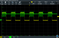
I am currently building a half-bridge with IRF3205 MOSFETs and the IR2112 driver. I have built the circuit largely in accordance with the data sheet.I have used two capacitors connected in parallel between VB and VS– a ceramic capacitor (100 nF) and anelectrolytic capacitor (22 µF). There is also a 22 µF electrolytic capacitor between COM and VCC. In addition, I have integrated a 1N5819 diode betweenVCC and VB.Atthe gates of the MOSFETs, 10 ? resistors are installed. Asinput signals, I am using a signal generator with two channels forHIN and LIN, both with a frequency of 10 kHz.I am using a combination of a coil connected in series with acapacitor (22 µF), which in turn is connected in parallel to a 10 ohm resistor, as the load.The problem that is currently occurring is that the gate signals of the twoMOSFETs are not completely square-wave.

Attachments
-
 27.9 KB Views: 0
Last edited by a moderator:


