
Sound amplifier and speaker compatibility with other electronic components (Motor and LED's)
- Thread starter Jacob1994
- Start date
Scroll to continue with content
Just a reminder that you will need 2 conductors through the slip ring, in case, in your enthusiasm, you overlooked that.
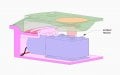
I have openings along the edge of the inner ring wall where I will try and connect the wire to.
I've created 7mm openings along the underside of the outside ring where I plan to connect the other wire to.
I modelled a small wall between the centre of the 2 rings to make sure they are unconnected.
Does my thinking behind the current configuration look correct?

Seems reasonable. You probably don't need the barrier but it won't hurt.I have openings along the edge of the inner ring wall where I will try and connect the wire to.
I've created 7mm openings along the underside of the outside ring where I plan to connect the other wire to.
I modelled a small wall between the centre of the 2 rings to make sure they are unconnected.
Does my thinking behind the current configuration look correct?
View attachment 238107
I must be missing something in the base you show. You say your limited in space to just the inner part shown, but why does the base even need to be made that way? There is plenty of space wasted in the radial segmented areas. All of those radial ribs/spokes wouldn't be necessary unless this is being made from some really heavy material. Just remove one rib and the wall into the motor chamber and there is plenty of area for larger batteries.
Ok that's great thanks.Seems reasonable. You probably don't need the barrier but it won't hurt.
One of my other points of concern I have is how shall I secure the DC motor to the base of the platform, since the securing holes only seem to be on the top of the motor?
Attachments
-
 207 KB Views: 5
Off the top of my head I’d make an indexing cavity in the base and use double sided foam tape.Ok that's great thanks.
One of my other points of concern I have is how shall I secure the DC motor to the base of the platform, since the securing holes only seem to be on the top of the motor?
Could I ask what you mean by indexing cavity, I can't seem to find any online references to it? Do you mean a small recess where the motor can be lowered to sit below?Off the top of my head I’d make an indexing cavity in the base and use double sided foam tape.
Yes, that's what I mean, alternatively a raised "rim" would work. The key is to have it index. The tape would be more than enough to fix it in place.Could I ask what you mean by indexing cavity, I can't seem to find any online references to it? Do you mean a small recess where the motor can be lowered to sit below?
Ok, well I plan on ordering the components first before I get the model 3D printed, so I can measure the exact dimensions of the motor and try and create a raised rim around the area. I'll use the tape as well to keep it held in place, hopefully the rim will provide it with a more robust fix.Yes, that's what I mean, alternatively a raised "rim" would work. The key is to have it index. The tape would be more than enough to fix it in place.
I must say I was very surprised that none of the motors have screw fixings on the underside, surely there must be other instances similar to my configuration?
Hi,
To summarize, I have very little knowledge of electronics, having had no hands-on experience since high school. I'm creating a rotating music box as an anniversary present for my wife and have so far managed to create the design you can see in the attached PDF. I have a 12V DC power supply which I'll be connecting to a 12v 6rpm worm gear motor (https://www.amazon.com/gp/product/B01MXPNX7P/ref=ewc_pr_img_4?smid=A1THAZDOWP300U&psc=1) and a 12v LED light strip (https://www.ebay.com/vod/FetchOrder...=I273304204472.N41.S2.typeITEM_SHIPPED.R1.TR1), as well as a sound chip (hopefully).
I'm hoping to play a song (3min 32sec) when the power button is pressed and after doing some research I've found the following products appear to provide what I'm looking for:
https://www.amazon.com/dp/B07P94Z9X...9Y2xpY2tSZWRpcmVjdCZkb05vdExvZ0NsaWNrPXRydWU=
https://www.amazon.com/DROK-Blue-Tooth-Board-Amplifier-Bundle/dp/B08GKBS4R2
I'm hoping if anyone here could let me know if there's a more suitable board I could use for my project or if the above boards are appropriate?
My main concerns are:
- Will the 12V power supply be enough to provide consistent power to the motor, LED's and the sound module?
- I'm intending to use 4 speakers for the output, however, I see that the diagram for the module only shows 2 connection points, can I double wire each of the connection points so I have 4 speakers?
- Should I have a fuse in my wiring to prevent any surge from damaging the components?
- Can I connect the sound module to any point in the electrical wiring or do I need to separately wire it to the 12V power input? (Do I need to do the same and keep the wiring for the motor and LED lights separate or can these also join in the same circuit?)
- If I incorporate a volume adjustment in the circuit will this affect the performance of the other components? i.e. increase/decrease rotation and light when the volume is increased/decreased?
Also, on a separate note, if I wanted to have the option for adjusting the light brightness would this as straightforward as just adding a dimmer switch into my design? My main concern is light/volume adjustments, affect the other electrical components, if someone could clarify if this is a legitimate thing I should be concerned with I'd be grateful.
I apologize for my lack of knowledge and I'd appreciate anyone with any expertise who could help me through this, this is far out of my league.
Thanks,
Jacob
Attachments
-
300.2 KB Views: 4
Hey Guys,
I'm looping you into a post I made on one of the other forums to let you know my progress, perhaps some of you may have experience in this area?
Hi,
To summarize, I have very little knowledge of electronics, having had no hands-on experience since high school. I'm creating a rotating music box as an anniversary present for my wife and have so far managed to create the design you can see in the attached PDF. I have a 12V DC power supply which I'll be connecting to a 12v 6rpm worm gear motor (https://www.amazon.com/gp/product/B01MXPNX7P/ref=ewc_pr_img_4?smid=A1THAZDOWP300U&psc=1) and a 12v LED light strip (https://www.ebay.com/vod/FetchOrder...=I273304204472.N41.S2.typeITEM_SHIPPED.R1.TR1), as well as a sound chip (hopefully).
I'm hoping to play a song (3min 32sec) when the power button is pressed and after doing some research I've found the following products appear to provide what I'm looking for:
https://www.amazon.com/dp/B07P94Z9X...9Y2xpY2tSZWRpcmVjdCZkb05vdExvZ0NsaWNrPXRydWU=
https://www.amazon.com/DROK-Blue-Tooth-Board-Amplifier-Bundle/dp/B08GKBS4R2
I'm hoping if anyone here could let me know if there's a more suitable board I could use for my project or if the above boards are appropriate?
My main concerns are:
- Will the 12V power supply be enough to provide consistent power to the motor, LED's and the sound module?
- I'm intending to use 4 speakers for the output, however, I see that the diagram for the module only shows 2 connection points, can I double wire each of the connection points so I have 4 speakers?
- Should I have a fuse in my wiring to prevent any surge from damaging the components?
- Can I connect the sound module to any point in the electrical wiring or do I need to separately wire it to the 12V power input? (Do I need to do the same and keep the wiring for the motor and LED lights separate or can these also join in the same circuit?)
- If I incorporate a volume adjustment in the circuit will this affect the performance of the other components? i.e. increase/decrease rotation and light when the volume is increased/decreased?
Also, on a separate note, if I wanted to have the option for adjusting the light brightness would this as straightforward as just adding a dimmer switch into my design? My main concern is light/volume adjustments, affect the other electrical components, if someone could clarify if this is a legitimate thing I should be concerned with I'd be grateful.
I apologize for my lack of knowledge and I'd appreciate anyone with any expertise who could help me through this, this is far out of my league.
Thanks,
Jacob
Attachments
-
300.2 KB Views: 1
I also found this board:
https://www.aliexpress.com/item/400...earchweb0_0,searchweb201602_,searchweb201603_
https://www.aliexpress.com/item/400...earchweb0_0,searchweb201602_,searchweb201603_
I also found this board:
https://www.aliexpress.com/item/400...earchweb0_0,searchweb201602_,searchweb201603_
https://www.aliexpress.com/item/400...earchweb0_0,searchweb201602_,searchweb201603_
Let's get serious here. Why do you need four speakers instead of one?
Are you holding a block party or is this an anniversary music card for the happy couple?
Do you know the difference between 5W output and 500W output?
Did you do a power analysis? How much current @12V or total power do all the devices take?
How many amperes or ampere-hours can your 12V supply provide?
Because the speakers are going to be very small, the size of the model is not very large so the speaker size is going to be limited. It also ties into the design of the structure.Let's get serious here. Why do you need four speakers instead of one?
Are you holding a block party or is this an anniversary music card for the happy couple?
Do you know the difference between 5W output and 500W output?
Did you do a power analysis? How much current @12V or total power do all the devices take?
How many amperes or ampere-hours can your 12V supply provide?
If I'm being totally honest, I have very little understanding when it relates to the typical electrical units of measurement and their relationship with each other.
The motors power requirements are as follows: Rated current 0.5A Stall current 1.3A
Link to motor: https://www.robotshop.com/en/12v-6rpm-reversible-high-torque-worm-gear-dc-motor.html
The LED's require 1A and a working power of 5W (I will be reducing the length of the LED strip so may not need as much power) https://www.ebay.com/itm/273304204472
I've not selected a 12V power supply yet, I was intending to use this jack socket though (https://www.walmart.ca/en/ip/5-5mmx...-Mount-Connector-DC-025M-5pcs/PRD3DEN29BT3O6A) unless this isn't appropriate for handling the above? The design of the base model requires that the jack socket I use have a fastening bolt located at the front as opposed to the rear.
I also had specified the following for the power switch however after comparing it now with the other items above I do not believe it is compatible. The fastening bolt for whichever power button switch it used also needs to be secured at the front, in a similar fashion to the power socket. https://www.amazon.com/DIYhz-Self-l...+hex&qid=1621064346&s=industrial&sr=1-51&th=1
Yeah, I've already got the slip rings sorted, am getting a couple of custom-size copper gaskets, only $10 each. Ordered them yesterdaySomething to maybe help understand the slip ring would be comparing it to a motor commutator but without the breaks that create the motor poles. So in essence a solid commutator. You might be able to make the rings from a raw copper clad pcb.


