Some transistor mix up....

Thread Starter

Miracletech

Joined Nov 15, 2019
160
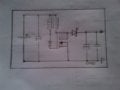
So I was designing a boost converter circuit with a BJT, but somehow, while doing research(like I always do) I found out that a MOSFET would be very much efficent. So I looked for a common one: IRF3205. My questions are;
1. Will the circuit actually run?
2. Will the mosfet have any issue because of no square wave input?
3.Let's assume that The dc input is 9v. Will the mosfet turn on because of the minimum vgs(th)?
4. Will a BJT be a better choice?
It is just a normal boost converter with a bjt, but in this case, the inductor is a torroid with primary and secondary winding. (Secondary to drain, primary to gate.)
 

Audioguru again

Joined Oct 21, 2019
6,826
Vgs(th) is the threshold where the Mosfet is turned on only a tiny amount (250uA which is only 0.25mA), it is almost turned off.
The datasheet of an IRF3205 shows that it turns on very well when Vgs is 10V, less turned on with 9V.

If the Mosfet input is not a squarewave then it will waste power when it is on the input voltage slopes.
A squarewave causes it to switch on quickly then Vds is low so wasted power is low, then it switches off quickly then current is zero so wasted power is zero.

You did not post your schematic so we do not know if a Mosfet will do anything in your circuit. "Transistor boost converter circuit" in Goggle shows 35 circuits on each page for about 8 pages.
 

Thread Starter

Miracletech

Joined Nov 15, 2019
160
Its just like a 1 transistor boost converter circuit using bjt, but this time, I want to turn things upper notch so I want to use a mosfet.

Just like this one:
And the one where the square wave input is the driving switch:
www.learnabout-electronics.org/PSU/psu32.php
Also, are There any mosfets that can turn on fully well with 3volts?
 

MisterBill2

Joined Jan 23, 2018
27,507
A.G. is correct in that without a specific circuit the best that you can get is GUESSES. So draw out the circuit on paper, clearly, and then either scan it or photograph it, and attach it to your next post. WE can provide good help if we have enough information, otherwise you will get a bunch of guesses that may not relate at all to your question.
 

Audioguru again

Joined Oct 21, 2019
6,826
My cheap solar garden lights use a simple voltage boost circuit like that.
I have seen some Mosfets that turn on fully with a Vgs of only 3V. Go to Digikey and search there.
 

Audioguru again

Joined Oct 21, 2019
6,826
An IRF540 datasheet tells you that its Vgs needs to be 10V for it to fully turn on.
An IRL540 turns on fully with a Vgs of only 5V and turns on pretty well with 4V. See the "L"? L means logic level.
 

Alec_t

Joined Sep 17, 2013
15,117
The 8N60 FET in that video has a 600V Vds rating, whereas the IRF540 rating is only 100V. Depending on the coil inductances, you may get >100V on the drain in that circuit and risk frying the FET (or bjt). The feedback voltage to the FET gate could also be excessive (>20V). Voltage limiting for both the drain and gate voltages would be advisable.
 

Thread Starter

Miracletech

Joined Nov 15, 2019
160
That means adding a gate and drain resistor right?
But the truth is: I wan to convert 9vdc to 96v or 90v dc output. Its for a home appliance.

The strange thing is in the video, he used no square wave input or any of such with a mosfet for that matter
 

Alec_t

Joined Sep 17, 2013
15,117
That means adding a gate and drain resistor right?
No. There is already a gate resistor. Zener diodes or Schottky diodes could be used to clamp gate and drain voltages to a safe level.
I wan to convert 9vdc to 96v or 90v dc output. Its for a home appliance.
What home appliance? The circuit shown is a low power one only.
To get 90V output at a current of, say, 1A would require the 9V battery to supply more than 1A x 90V/9V = 10A.
If your 9V source is a little PP3 battery then that would be impossible. If the battery can supply only 100mA, for example, then the maximum output current of the converter would be less than 10mA. If Volts go up the current comes down.
The strange thing is in the video, he used no square wave input or any of such with a mosfet for that matter
The circuit does not use a square wave source. The gate is driven by the voltage pulse generated in the secondary winding over the inductor, as a result of transformer action.
 

Thread Starter

Miracletech

Joined Nov 15, 2019
160
No. There is already a gate resistor. Zener diodes or Schottky diodes could be used to clamp gate and drain voltages to a safe level.

What home appliance? The circuit shown is a low power one only.
To get 90V output at a current of, say, 1A would require the 9V battery to supply more than 1A x 90V/9V = 10A.
If your 9V source is a little PP3 battery then that would be impossible. If the battery can supply only 100mA, for example, then the maximum output current of the converter would be less than 10mA. If Volts go up the current comes down.

The circuit does not use a square wave source. The gate is driven by the voltage pulse generated in the secondary winding over the inductor, as a result of transformer action.
Dc input is ~9v 4a
 

MisterBill2

Joined Jan 23, 2018
27,507
OK, in posts #13 and #18 we finally learn the desired output voltage and the available source power, volts and amps. The challenge is that the voltage step up is over 1:10, which is rather high for a simple converter. Also, the maximum available input power would be 36 watts (9V x 4A), and so at 100% efficiency the output could be 0.30 amps. With no clue as to the desired power out it becomes confusing, and a lot more complex. So here is where more information is needed, since there are real limits on what could be achieved.

If I could design equipment that exceeded 100% efficiency I would be quite wealthy, even very rich.
And unfortunately I would not be able to share those designs in this forum.
 

Audioguru again

Joined Oct 21, 2019
6,826
High efficiency means low losses. Use a Cmos squarewave oscillator that draws almost no current. It and a Cmos inverter drive two NPN and PNP emitter follower buffers that drive the gates of two Mosfets that drive the transformer push-pull.
 

MisterBill2

Joined Jan 23, 2018
27,507
High efficiency means low losses. Use a Cmos squarewave oscillator that draws almost no current. It and a Cmos inverter drive two NPN and PNP emitter follower buffers that drive the gates of two Mosfets that drive the transformer push-pull.
The original post was showing a switching power supply circuit which under ideal conditions nay be more efficient than an inverter with a transformer and rectifiers. AND, even with 100% efficiency it is not likely that with 36 watts in there will be over 36 watts out. And 30 watts is not enough for any useful kitchen appliance that I am aware of. So at this point I ask just what the TS is planning on powering with the sought-after power inverter circuit, and just how much power does that device require. A whole lot more information is required before anything better than guesses can be provided.
 

Thread Starter

Miracletech

Joined Nov 15, 2019
160
OK. Its time I come straight. The circuit is a security system with alarm and others. I WANT TO JUST MAKE IT SIMPLE AND EASY without any Ic component here. I want to add more FET'S ''IF I GET THE DESIRED OUTPUT''. I like circuits that even a 5 year old can learn.

If everybody remembers, I asked:
''4. Will a BJT be a better choice?''
 
Top