SN74151AN: Help understanding HIGH/LOW selector inputs.

Thread Starter

atrumblood

Joined May 13, 2012
59
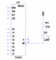
The pot is being used as a rheostat for the LM317. It's how I adjust the regulator.. I have it dialed in right now to 5.1V. I have attached the schematic.

The Vout of the regulator is hooked to the top 2nd rail down.


That would suck if I burned it out.

So let's put a side for a moment that I may have burnt the chip out. I have everything hooked up right don't I?
 

Attachments

Ron H

Joined Apr 14, 2005
7,063
I don't see anything wrong with your breadboard. You should not have an adjustable supply. R1 should be 100-120 ohms, and R2 should be 3 times that value (100/300, 110/330, or 120/360).
TTL can sink much more current than it can source. As it is, your current is not predictable, and too high for a sourcing TTL output. You should connect the cathode of your LED to W, and connect a series current limiting resistor (270 ohms) from the anode to +5V. This will still turn the LED on when the D input is high, and off when low (if your device is working).
 

Thread Starter

atrumblood

Joined May 13, 2012
59
Thank you Ron H. I will give your instructions a try and let you know if I have any further questions. I hope the chip isn't burnt out but if it is I am sure I have another multiplexer I can test out.
 

Thread Starter

atrumblood

Joined May 13, 2012
59
Ron,

Thanks again for you help, and of course to the others who contributed.

Just a quick update. It seems as though the chip still works, but it is working differently than I would have thought. Probably another misunderstanding on my part.

While I have the led plugged into the W pin the led stays on. It goes off when I tie D0 to ground. Does this have anything to do with the inputs on W having the overscore on them?
 

Ron H

Joined Apr 14, 2005
7,063
Ron,

Thanks again for you help, and of course to the others who contributed.

Just a quick update. It seems as though the chip still works, but it is working differently than I would have thought. Probably another misunderstanding on my part.

While I have the led plugged into the W pin the led stays on. It goes off when I tie D0 to ground. Does this have anything to do with the inputs on W having the overscore on them?
Did you wire it like this? Note that the LED does NOT connect to ground.
 

Attachments

Ron H

Joined Apr 14, 2005
7,063
Ron,

Thanks again for you help, and of course to the others who contributed.

Just a quick update. It seems as though the chip still works, but it is working differently than I would have thought. Probably another misunderstanding on my part.

While I have the led plugged into the W pin the led stays on. It goes off when I tie D0 to ground. Does this have anything to do with the inputs on W having the overscore on them?
Sorry, I was momentarily confused. As I said in post #22,
This will still turn the LED on when the D input is high, and off when low (if your device is working).
This is because, as you surmised, W (with the bar over it, or the bubble on the output) is the complement (inversion) of Y.
So, when the D input is high, W is low, which turns on the LED.
 

Thread Starter

atrumblood

Joined May 13, 2012
59
Awesome, this helps my understanding a lot being able to see one in action. Plus I found another 74151 and verified that pins Y and W both work with W inverted to Y

I will be starting up a new thread sometime soon as I continue learning.

Thanks again Ron.
 
Last edited:
Top