Facebook
 Google
 GitHub
 Linkedin
sorry for replying lateI assumed anyone interested would have run the sim for themselves.
i was held up with assignments
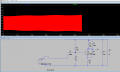
I tried changing 470 to 1k and inductance to 50n and skip initial op soln. but I see no difference in the output of the first stage
check this out:
Attachments
-
2.4 KB Views: 6