Simple circuit to give a ON pulse and OFF pulse

AnalogKid

Joined Aug 1, 2013
12,222
As GPIO inputs, these should *not* draw 2 mA from whatever is driving them, let alone 200 mA. Why do you think the input current is so high?

Also, where are you located?

ak
 

Thread Starter

vikrambharath

Joined Aug 13, 2018
17
Thank you guys for all the valuable information given.

Thank you AK for post #16 it is working perfectly.
I live in south India BTW.

For the current draw, it was my mistake.

Thank you Dana for #23 it was really helpful.
 

Picbuster

Joined Dec 2, 2013
1,060
I need a simple circuit which will give a 100ms 5v pulse when an SPST switch is turned ON (i.e constant input) and a same 100ms 5v pulse when the SPST switch is turned OFF.Please help.View attachment 158175
Most simple solution:
use a PIC ( smallest one) interrupt on up and low going edge from input.
Generate a 100mS pulse on interrupt.
Use Pic timer_x to create pulse.

Want power output? add a p channel mosfet.

This a less than 1 hour job.

Picbuster
 

danadak

Joined Mar 10, 2018
4,057
Here is a solution using Bascom AVR, their Basic language. IDE is free for

small projects like this.


https://www.mcselec.com/index.php?option=com_content&task=view&id=14&Itemid=103


Uses ATTINY85, 1 R (button pulldown), one button, one cap to bypass ATTINY85.


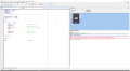
Code looks like –

upload_2018-9-3_20-40-18.png


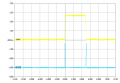
Output is –


upload_2018-9-3_20-40-1.png

Top trace button press followed by release, time in between is arbitrary.

Bottom trace is output, 100 mS pulse, triggered by each edge, width your choosing. Accuracy is

quite good.


Regards, Dana.
 
Top